содержание .. 392 393 394 395 ..
Toyota Sequoia (2005). Manual - part 394
H41440
H23351
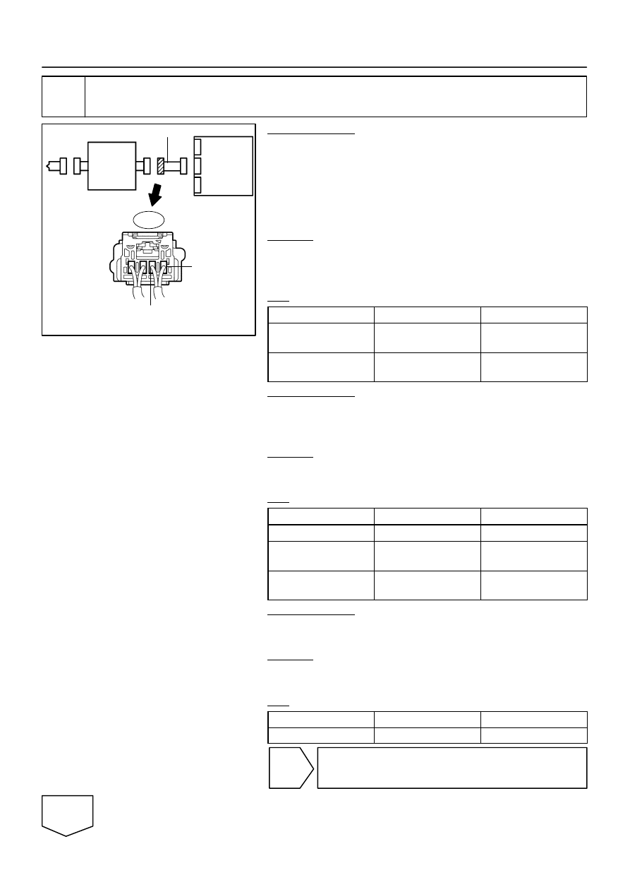
D Squib
Spiral
Cable
Airbag
Sensor
Assembly
D+
D–
C
D
E
F
A
B
Cowl Wire
A23
–
DIAGNOSTICS
SUPPLEMENTAL RESTRAINT SYSTEM
DI–1371
1565
21
Check cowl wire.
PREPARATION:
(a)
Restore the released activation prevention mechanism of
connector ”B” to the original condition.
(b)
Disconnect the the cowl wire connector from the spiral
cable.
(c)
Connect the negative (–) terminal cable to the battery,
and wait for at least 2 seconds.
CHECK:
(a)
Turn the ignition switch to the ON position.
(b)
Measure the voltage according to the value(s) in the table
below.
OK:
Tester Connection
Condition
Specified Condition
A23–1 (D+) –
Body ground
Ignition switch ON
Below 1 V
A23–2 (D–) –
Body ground
Ignition switch ON
Below 1 V
PREPARATION:
(a)
Turn the ignition switch to the LOCK position.
(b)
Disconnect the negative (–) terminal cable from the bat-
tery, and wait for at least 90 seconds.
CHECK:
Measure the resistance according to the value(s) in the table
below.
OK:
Tester Connection
Condition
Specified Condition
A23–1 (D+) – A23–2 (D–)
Always
Below 1
Ω
A23–1 (D+) –
Body ground
Always
1 M
Ω
or higher
A23–2 (D–) –
Body ground
Always
1 M
Ω
or higher
PREPARATION:
Release the activation prevention mechanism built into con-
nector ”B” (see page
CHECK:
Measure the resistance according to the value(s) in the table
below.
OK:
Tester Connection
Condition
Specified Condition
A23–1 (D+) – A23–2 (D–)
Always
1 M
Ω
or higher
NG
Repair or replace cowl wire.
OK