Content .. 2692 2693 2694 2695 ..
Toyota Tundra (2015 year). Manual - part 2694
JUNCTION BLOCK ASSEMBLY)
25.
CHECK HARNESS AND CONNECTOR (MAIN BODY ECU - BATTERY AND BODY
GROUND)
(a) Connect the cable to the negative (-) battery terminal.
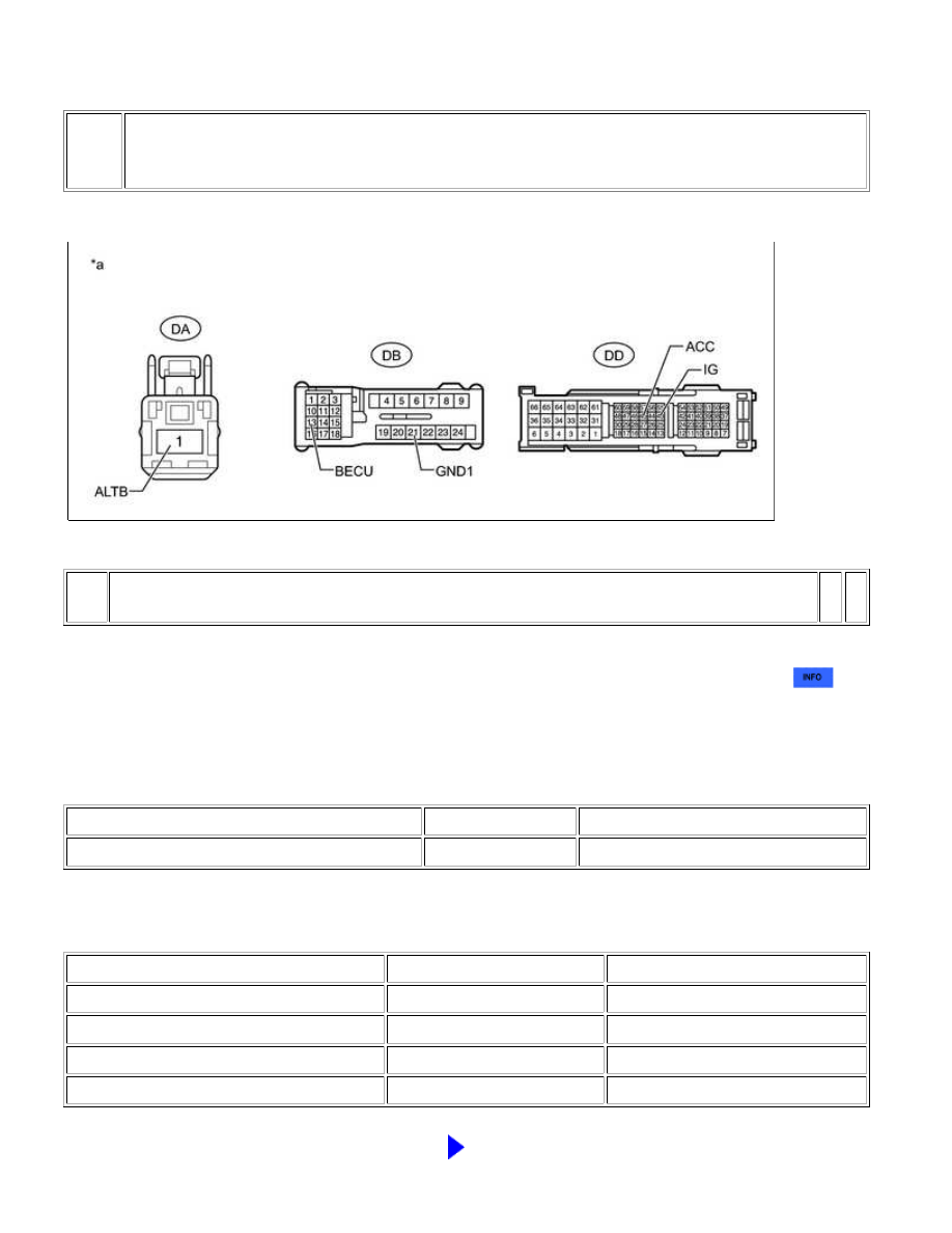
Text in Illustration
*a
-
-
NOTICE:
When disconnecting the cable, some systems need to be initialized after the cable is reconnected
.
(b) Disconnect the DA, DB and DD main body ECU (driver side junction block assembly) connectors.
(c) Measure the resistance according to the value(s) in the table below.
Standard Resistance:
TESTER CONNECTION
CONDITION
SPECIFIED CONDITION
DB-21 (GND1) - Body ground
Always
Below 1 Ω
(d) Measure the voltage according to the value(s) in the table below.
Standard Voltage:
TESTER CONNECTION
CONDITION
SPECIFIED CONDITION
DA-1 (ALTB) - Body ground
Always
11 to 14 V
DB-13 (BECU) - Body ground
Always
11 to 14 V
DD-43 (IG) - Body ground
Ignition switch ON
11 to 14 V
DD-45 (ACC) - Body ground
Ignition switch ACC
11 to 14 V
NG
REPAIR OR REPLACE HARNESS OR CONNECTOR
CAN COMMUNICATION: CAN COMMUNICATION SYSTEM: U1002;...