Toyota Tundra (2015 year). Manual - part 247


  Index      Toyota     Toyota Tundra (2015 year) - Service and Repair Manual


Search            copyright infringement  


Content   ..  245  246  247  248   ..


Toyota Tundra (2015 year). Manual - part 247


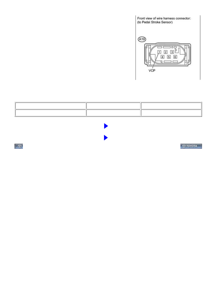
(a) Disconnect the A19 sensor connector.

(b) Measure the voltage according to the value(s) in the table below.

Standard Voltage:

TESTER CONNECTION

SWITCH CONDITION

SPECIFIED CONDITION

A19-1 (VCP) - Body ground

Ignition switch ON

5.0 V

NG

REPLACE VSC ACTUATOR ASSEMBLY

OK

REPLACE BRAKE BOOSTER ASSEMBLY

BRAKE CONTROL: VEHICLE STABILITY CONTROL SYSTEM: C...

Last Modified: 9-16-2014

6.6 C

Doc ID: RM000001HY403IX

Model Year: 2015

Model: Tundra

Prod Date Range: [08/2014 -           ]

Title: BRAKE CONTROL: VEHICLE STABILITY CONTROL SYSTEM: C1249/49; Open in Stop Light Switch Circuit;

2015 MY Tundra [08/2014 -        ]

DTC

C1249/49 Open in Stop Light Switch Circuit

DESCRIPTION

The skid control ECU detects the brake operating conditions through a signal transmitted by the stop light switch.

The skid control ECU incorporates an open circuit detection circuit.

DTC

CODE

DTC DETECTION CONDITION

TROUBLE AREA

C1249/49

to 2.2 V for 2.5 second.

1. 

When pressure sensor signal indicates pressure increase, but

stop light switch signal does not change.

2. 

3. 

While vehicle is accelerated to higher than 40 km/h (24.9 mph)

and then decelerated to less than 3 km/h (1.9 mph), stop light

switch signal change from OFF to ON is not detected (4 trip

detection logic).

4. 

ECU-IG1 NO.

1 fuse

STOP fuse

Stop light

control relay

Stop light

switch

Stop light

switch circuit

VSC actuator

assembly

WIRING DIAGRAM

BRAKE CONTROL: VEHICLE STABILITY CONTROL SYSTEM: C...

INSPECTION PROCEDURE

NOTICE:

When replacing the VSC actuator assembly, perform zero point calibration 


.

PROCEDURE

1.

INSPECT FUSE (STOP)

BRAKE CONTROL: VEHICLE STABILITY CONTROL SYSTEM: C...

OK

(a) Remove the STOP fuse from the engine room relay block.

(b) Measure the resistance according to the value(s) in the table below.

Standard Resistance:

TESTER CONNECTION

CONDITION

SPECIFIED CONDITION

STOP fuse

Always

Below 1 Ω

NG

CHECK FOR SHORTS IN ALL HARNESSES AND

CONNECTORS CONNECTED TO FUSE AND REPLACE

FUSE

2.

INSPECT STOP LIGHT CONTROL RELAY (BRK NO. 1, BRK NO. 2)

(a) Remove the stop light control relays (BRK NO. 1 and BRK NO.

2) from the engine room relay block.

(b) Measure the resistance according to the value(s) in the table below.

Standard Resistance:

for BRK NO. 1

for BRK NO. 2

TESTER CONNECTION

CONDITION

SPECIFIED CONDITION

BRAKE CONTROL: VEHICLE STABILITY CONTROL SYSTEM: C...


Content   ..  245  246  247  248   ..