Content .. 2070 2071 2072 2073 ..
Toyota Tundra (2015 year). Manual - part 2072
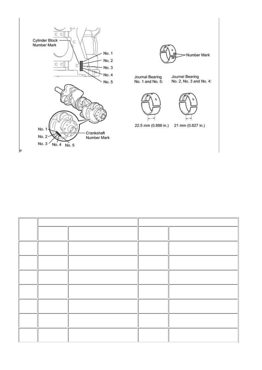
Example:
Cylinder block "07" + Crankshaft "06" = Total number 13 (Use upper bearing "6" and lower bearing "7")
HINT:
A = Cylinder block number mark
B = Crankshaft number mark
Standard bearing center wall thickness:
No. 1 and No. 5 journals
(A) +
(B)
UPPER BEARING
LOWER BEARING
NUMBER
MARK
SPECIFIED CONDITION
NUMBER
MARK
SPECIFIED CONDITION
00 to 02 4
2.501 to 2.504 (0.0985 to 0.0986
in.)
5
2.488 to 2.491 (0.0980 to 0.0981
in.)
03 to 05 5
2.504 to 2.507 (0.0986 to 0.0987
in.)
5
2.488 to 2.491 (0.0980 to 0.0981
in.)
06 to 08 5
2.504 to 2.507 (0.0986 to 0.0987
in.)
6
2.491 to 2.494 (0.0981 to 0.0982
in.)
09 to 11 6
2.507 to 2.510 (0.0987 to 0.0988
in.)
6
2.491 to 2.494 (0.0981 to 0.0982
in.)
12 to 14 6
2.507 to 2.510 (0.0987 to 0.0988
in.)
7
2.494 to 2.497 (0.0982 to 0.0983
in.)
15 to 17 7
2.510 to 2.513 (0.0988 to 0.0989
in.)
7
2.494 to 2.497 (0.0982 to 0.0983
in.)
18 to 20 7
2.510 to 2.513 (0.0988 to 0.0989
in.)
8
2.497 to 2.500 (0.0983 to 0.0984
in.)
3UR-FE ENGINE MECHANICAL: CYLINDER BLOCK: INSPECTIO...