Content .. 1890 1891 1892 1893 ..
Toyota Tundra (2015 year). Manual - part 1892
IAT sensor voltage [IAT]
Less than 0.18 V [More than 128°C (262.4°F)]
P0113:
IAT sensor voltage [IAT]
More than 4.91 V [Less than -55°C (-67°F)]
COMPONENT OPERATING RANGE
IAT sensor voltage [IAT]
0.18 to 4.91 V [-55 to 128°C (-67 to 262.4°F)]
CONFIRMATION DRIVING PATTERN
Connect the Techstream to the DLC3.
1.
Turn the ignition switch to ON and turn the Techstream on.
2.
Clear DTCs (even if no DTCs are stored, perform the clear DTC operation).
3.
Turn the ignition switch off and wait for at least 30 seconds.
4.
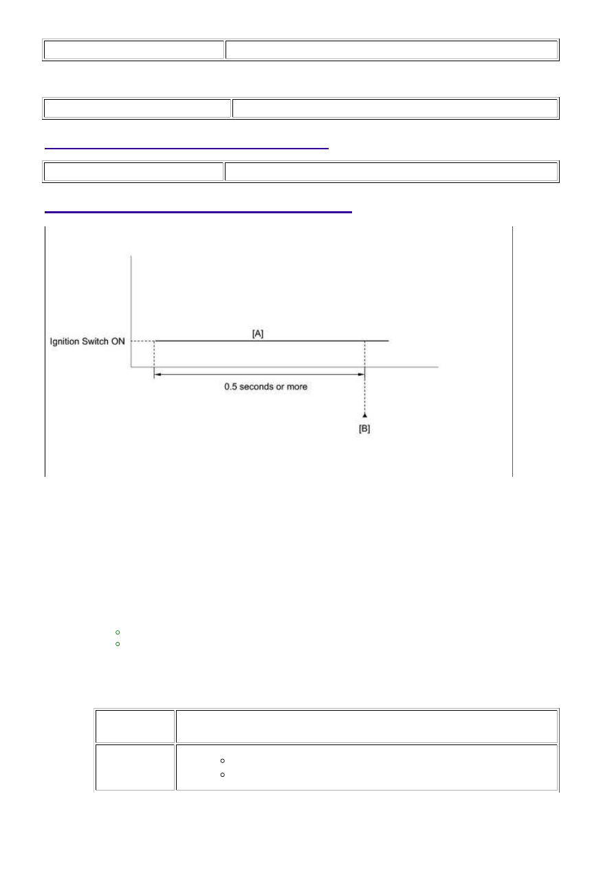
Turn the ignition switch to ON and turn the Techstream on.
5.
Wait 0.5 seconds or more [A].
6.
Enter the following menus: Powertrain / Engine and ECT / Trouble Codes [B].
7.
Read the Pending DTCs.
HINT:
If a pending DTC is output, the system is malfunctioning.
If a pending DTC is not output, perform the following procedure.
8.
Enter the following menus: Powertrain / Engine and ECT / Utility / All Readiness.
9.
Input the DTC: P0112 or P0113.
10.
Check the DTC judgment result.
TESTER
DISPLAY
DESCRIPTION
NORMAL
DTC judgment completed
System normal
11.
3UR-FE ENGINE CONTROL SYSTEM: SFI SYSTEM: P0112,P0113; ...