Content .. 1856 1857 1858 1859 ..
Toyota Tundra (2015 year). Manual - part 1858
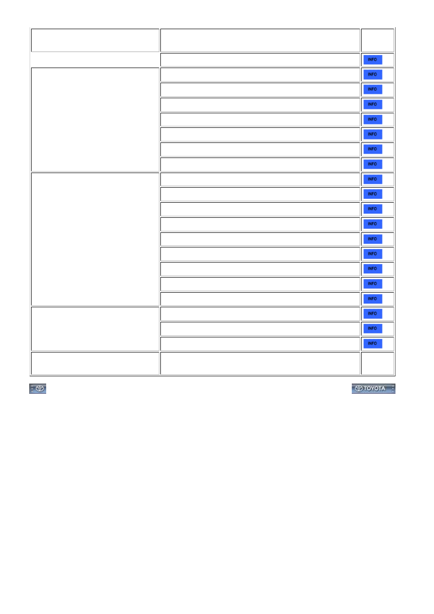
SYMPTOM
SUSPECTED AREA
SEE
PAGE
Brake override system
Surging (Poor driveability)
Spark plug
Fuel pump control circuit
Ignition system
Injector
Mass air flow meter
Variable valve timing system
Compression
Engine stalls soon after starting
Fuel pump control circuit
Spark plug
Ignition system
Injector
Variable valve timing system
Electronic throttle control system
Air induction system
PCV hose
Compression
Engine stalls only during A/C
operation
A/C signal circuit (for Automatic Air Conditioning System)
A/C signal circuit (for Manual Air Conditioning System)
ECM
Unable/difficult to refuel
Fuel system (canister, refueling valve, roll over valve, fuel
tank, etc.)
-
3UR-FE ENGINE CONTROL SYSTEM: SFI SYSTEM: PROBLEM ...