Toyota Tundra (2015 year). Manual - part 1280


  Index      Toyota     Toyota Tundra (2015 year) - Service and Repair Manual


Search            copyright infringement  


Content   ..  1278  1279  1280  1281   ..


Toyota Tundra (2015 year). Manual - part 1280


try again.

1. 

Turn the ignition switch off.

2. 

Connect the Techstream to the DLC3.

3. 

Turn the ignition switch to ON.

4. 

Turn the Techstream on.

5. 

Clear DTCs (if set) 


.

6. 

Turn the ignition switch off and wait for at least 30 seconds.

7. 

Turn the ignition switch to ON and turn the Techstream on.

8. 

Enter the following menus: Powertrain / Engine and ECT / Utility / Secondary Air Injection Check /

Automatic Mode.

9. 

Start the engine after the Techstream initialization is finished.

10. 

Perform the System Check operation by pressing ENTER (Next).

11. 

Perform the following to confirm the AIR system pending codes: Press ENTER (Exit).

12. 

Check for pending DTCs.

OK:

No pending DTC is output.

13. 

After the "Secondary air injection check" is completed, check for All Readiness by entering the

following menus: Powertrain / Engine and ECT / Utility / All Readiness.

14. 

Input the DTC: P2440, P2441, P2442 or P2443.

15. 

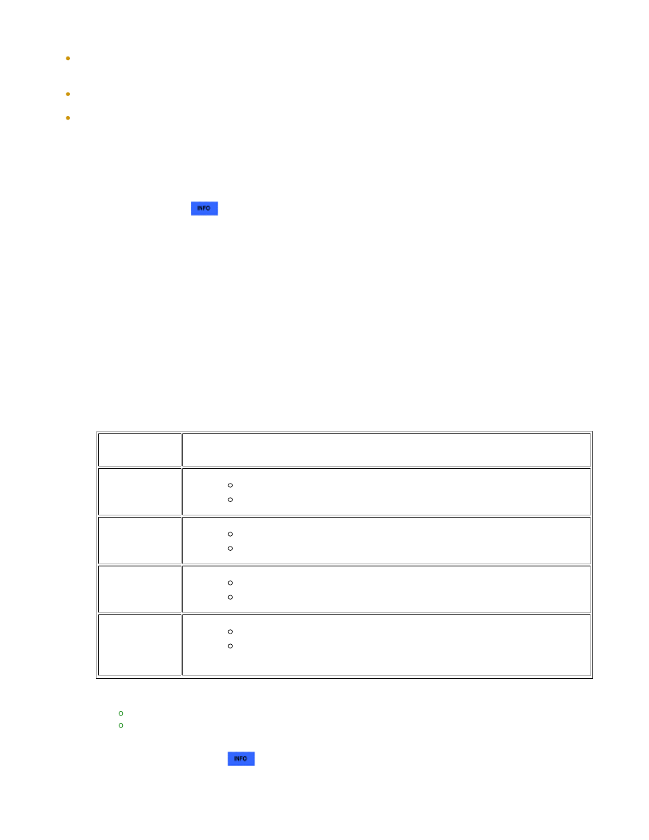
Check the DTC judgment result.

TESTER

DISPLAY

DESCRIPTION

NORMAL

DTC judgment completed

System normal

ABNORMAL

DTC judgment completed

System abnormal

INCOMPLETE

DTC judgment not completed

Perform driving pattern after confirming DTC enabling conditions

N/A

Unable to perform DTC judgment

HINT:

If the judgment result shows NORMAL, the system is normal.
If the judgment result shows ABNORMAL, the system has a malfunction.

16. 

If the test result is INCOMPLETE or N/A and no pending DTC is output, perform a universal trip and

check for permanent DTCs 


.

HINT:

17. 

1UR-FE ENGINE CONTROL SYSTEM: SFI SYSTEM: P2440-P2443;...

If no permanent DTC is output, the system is normal.
If a permanent DTC is output, the system is malfunctioning.

Turn the ignition switch off.

18. 

WIRING DIAGRAM

Refer to DTC P0412 


.

INSPECTION PROCEDURE

HINT:

Bank 1 refers to the bank that includes the No. 1 cylinder*.

*: The No. 1 cylinder is the cylinder which is farthest from the transmission.

Bank 2 refers to the bank that does not include the No. 1 cylinder.

HINT:

Determination by ECM monitoring:

The ECM locates malfunctions in the Secondary Air Injection (AIR) system by detecting the pressure in the

AIR passage between the air pump and Air Switching Valve (ASV) and stores a DTC. Soon after a cold
engine start, the monitor runs for a short time while the AIR system is both ON and OFF. The ECM detects
both the pressure and the exhaust pulsation and compares them.

The following 8 patterns are AIR system pressure conditions in the AIR system passage.

Pressure Condition in Secondary Air Injection System Case 1

Air Pump

ON

Air Switching Valve

Open

Pressure

1.9 kPa or more

Pulsation Detection

Exhaust gas pulsation detected

Pressure Condition in Secondary Air Injection System Case 2

Air Pump

OFF

Air Switching Valve

Open

Pressure

Less than 3.0 kPa

Pulsation Detection

Exhaust gas pulsation detected

Pressure Condition in Secondary Air Injection System Case 3

Air Pump

ON

Air Switching Valve

Closed

Pressure

1.9 kPa or more

Pulsation Detection

Exhaust gas pulsation not detected

Pressure Condition in Secondary Air Injection System Case 4

Air Pump

OFF

1UR-FE ENGINE CONTROL SYSTEM: SFI SYSTEM: P2440-P2443;...

Air Switching Valve

Closed

Pressure

Less than 3.0 kPa

Pulsation Detection

Exhaust gas pulsation not detected

Pressure Condition in Secondary Air Injection System Case 5

Air Pump

ON

Air Switching Valve

Open

Pressure

1.9 kPa or more

Pulsation Detection

Exhaust gas pulsation detected

Pressure Condition in Secondary Air Injection System Case 6

Air Pump

OFF

Air Switching Valve

Open

Pressure

Less than 3.0 kPa

Pulsation Detection

Exhaust gas pulsation detected

Pressure Condition in Secondary Air Injection System Case 7

Air Pump

ON

Air Switching Valve

Closed

Pressure

1.9 kPa or more

Pulsation Detection

Exhaust gas pulsation not detected

Pressure Condition in Secondary Air Injection System Case 8

Air Pump

OFF

Air Switching Valve

Closed

Pressure

Less than 3.0 kPa

Pulsation Detection

Exhaust gas pulsation not detected

If the detected pressure is high, the air pump is assumed to be ON and if it alternates sharply, the ASV is

HINT:

The exhaust pulsation value is calculated in the ECM. If the calculated value exceeds a certain level, the

ECM determines that the exhaust pulsation is in the AIR system.

HINT:

DETECTED CONDITION

WHILE AIR OPERATING:

AIR PUMP ON, ASV OPEN

DETECTED CONDITION WHILE

AIR NOT OPERATING:

AIR PUMP OFF, ASV CLOSED

ECM DETERMINATION

DTC

OUTPUT

Case 1

Case 8

Normal

-

Case 1

Case 6

Air switching valve stuck open

P2440

or

P2442

Case 1

Case 7

Air pump stuck ON

P2444

or

P2446

Case 2

Case 8

Air pump stuck OFF

P2445

or

P2447

Case 3

Case 8

Air switching valve stuck closed

P2441

or

P2443

Case 1

Case 5

Air switching valve stuck open and

air pump stuck ON

P2440 and

P2444

or

P2442 and

P2446

Case 2

Case 6

Air switching valve stuck open and

air pump stuck OFF

P2440 and

P2445

or

P2442 and

P2447

Case 3

Case 7

Air switching valve stuck closed

and air pump stuck ON

P2441 and

P2444

or

P2443 and

P2446

Case 4

Case 8

Air switching valve stuck closed

and air pump stuck OFF

P2441 and

P2445

or

P2443 and

P2447

HINT:

By using the Techstream to perform the Secondary Air Injection Check operation in the System Check, the
air-fuel ratio and the pressure in the secondary air injection system passage can be checked while the
secondary air injection system is operating. This helps technicians to troubleshoot the system when it
malfunctions. Furthermore, pending codes also can be checked by performing Utility / Secondary Air
Injection Check / Automatic Mode after the repair.
Read freeze frame data using the Techstream. Freeze frame data records the engine condition when
malfunctions are detected. When troubleshooting, freeze frame data can help determine if the vehicle was
moving or stationary, if the engine was warmed up or not, if the air-fuel ratio was lean or rich, and other
data from the time the malfunction occurred.

System Check:

1UR-FE ENGINE CONTROL SYSTEM: SFI SYSTEM: P2440-P2443;...


Content   ..  1278  1279  1280  1281   ..