Toyota Tundra. Manual - part 297


  Index      Toyota     Toyota Tundra (2007-2010 year) - Service and Repair Manual


Search            copyright infringement  


Content   ..  295  296  297  298   ..


Toyota Tundra. Manual - part 297


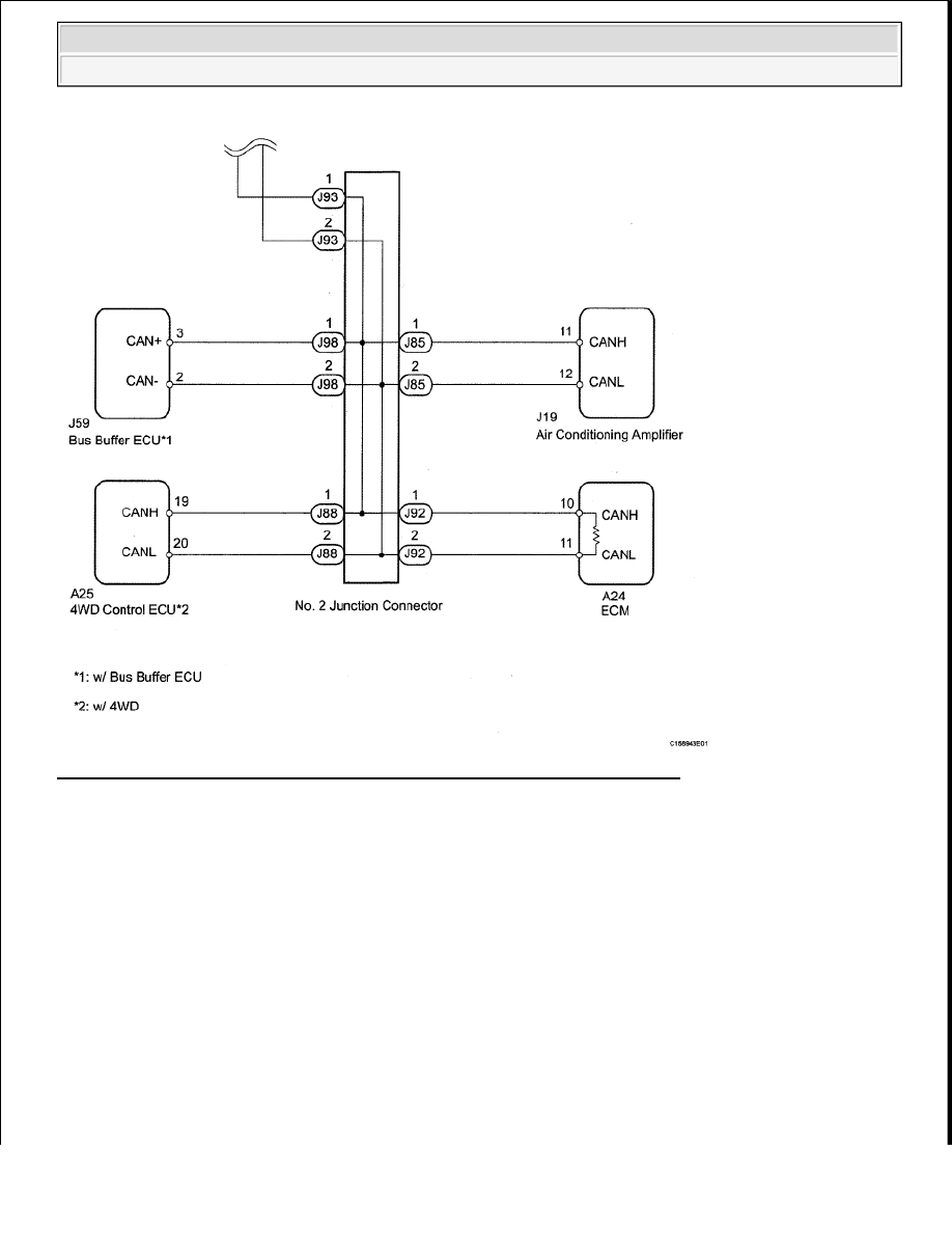
Fig. 113: Identifying Short To B+ In CAN Bus Line - Wiring Diagram (2 Of 2) 
Courtesy of TOYOTA MOTOR SALES, U.S.A., INC. 

INSPECTION PROCEDURE 

HINT: 

Operating the ignition switch, any switches or any doors triggers related ECU and sensor communication with 
the CAN, which causes resistance variation. 

1. DISCONNECT CABLE FROM NEGATIVE BATTERY TERMINAL 

a. Disconnect the cable from the negative (-) battery terminal before measuring the resistances of the 

main wire and the branch wire. 

CAUTION: Wait at least 90 seconds after disconnecting the cable from the 

negative (-) battery terminal to prevent airbag and seat belt 
pretensioner activation.


2009 Toyota Tundra 

2009 ACCESSORIES & EQUIPMENT CAN Communication - Tundra


2. CHECK FOR SHORT TO B+ IN CAN BUS WIRE (DLC3 BRANCH WIRE) 

a. Disconnect the J86 No. 1 junction connector connector.  

b. Measure the resistance according to the value(s) in the table below. 

Result  

RESULT REFERENCE TABLE 

Fig. 114: Identifying J17 DLC3 Connector Terminal 
Courtesy of TOYOTA MOTOR SALES, U.S.A., INC. 

NG: REPAIR OR REPLACE CAN BRANCH WIRE CONNECTED TO DLC3 (CANH, CANL)  

OK: Go to next step  

3. CONNECT CONNECTOR 

a. Reconnect the J86 No. 1 junction connector connector.  

4. CHECK FOR SHORT TO B+ IN CAN BUS WIRE (NO. 2 JUNCTION CONNECTOR SIDE) 

a. Disconnect the J93 No. 2 junction connector connector.  

b. Measure the resistance according to the value(s) in the table below. 

Result  

RESULT REFERENCE TABLE 

NOTE:

After the ignition switch is turned OFF, the navigation system 
requires approximately 90 seconds to record various types of 
memory and settings. As a result, after turning the ignition switch 
OFF, wait 90 seconds or more before disconnecting the cable from 
the negative (-) battery terminal.

Tester Connection

Switch Condition Measured Resistance Proceed to

J17-6 (CANH) - J17-16 (BAT)

Ignition switch OFF

1 ohms or higher

OK

J17-14 (CANL) - J17-16 (BAT)

J17-6 (CANH) - J17-16 (BAT)

Ignition switch OFF

Below 1 ohms

NG

J17-14 (CANL) - J17-16 (BAT)


2009 Toyota Tundra 

2009 ACCESSORIES & EQUIPMENT CAN Communication - Tundra


Fig. 115: Identifying J17 DLC3 Connector Terminal 
Courtesy of TOYOTA MOTOR SALES, U.S.A., INC. 

NG: Go to step 17 

OK: Go to next step  

5. CHECK FOR SHORT TO B+ IN CAN BUS WIRE (NO. 1 JUNCTION CONNECTOR - NO. 2 

JUNCTION CONNECTOR) 

a. Disconnect the J94 No. 1 junction connector connector.  

b. Measure the resistance according to the value(s) in the table below. 

Result  

RESULT REFERENCE TABLE 

Tester Connection

Switch Condition Measured Resistance Proceed to

J17-6 (CANH) - J17-16 (BAT)

Ignition switch OFF

1 ohms or higher

OK

J17-14 (CANL) - J17-16 (BAT)

J17-6 (CANH) - J17-16 (BAT)

Ignition switch OFF

Below 1 ohms

NG

J17-14 (CANL) - J17-16 (BAT)

Tester Connection

Switch Condition Measured Resistance Proceed to

J94-1 (CANH) - J17-16 (BAT)

Ignition switch OFF

1 ohms or higher

OK

J94-2 (CANL) - J17-16 (BAT)

J94-1 (CANH) - J17-16 (BAT)

Ignition switch OFF

Below 1 ohms

NG

J94-2 (CANL) - J17-16 (BAT)


2009 Toyota Tundra 

2009 ACCESSORIES & EQUIPMENT CAN Communication - Tundra


Fig. 116: Identifying J94 No. 1 Junction Connector 
Courtesy of TOYOTA MOTOR SALES, U.S.A., INC. 

NG: REPAIR OR REPLACE CAN MAIN WIRE OR CONNECTOR (NO. 1 JUNCTION 
CONNECTOR - NO. 2 JUNCTION CONNECTOR)
  

OK: Go to next step  

6. CONNECT CONNECTOR 

a. Reconnect the J94 No. 1 junction connector connector.  

b. Reconnect the J93 No. 2 junction connector connector.  

7. CHECK FOR SHORT TO B+ IN CAN BUS WIRE (NO. 1 JUNCTION CONNECTOR - 

COMBINATION METER ECU) 

a. Disconnect the J84 No. 1 junction connector connector.  

b. Measure the resistance according to the value(s) in the table below. 

Result  

RESULT REFERENCE TABLE 

Tester Connection

Switch Condition Measured Resistance Proceed to

J84-1 (CANH) - J17-16 (BAT)


2009 Toyota Tundra 

2009 ACCESSORIES & EQUIPMENT CAN Communication - Tundra


Content   ..  295  296  297  298   ..