Content .. 2832 2833 2834 2835 ..
Toyota Tundra. Manual - part 2834
MONITOR DESCRIPTION
These DTCs indicate an open or short in the shift solenoid valve S4 circuit. When there is an open or short
circuit in any shift solenoid valve circuit, the ECM detects the problem, illuminates the MIL and stores the
DTC. When the shift solenoid valve S4 is ON, if its resistance is 8 ohms or less, the ECM determines there is a
short in the shift solenoid valve S4 circuit.
When the shift solenoid valve S4 is OFF, if its resistance is 100 kohms or more, the ECM determines there is an
open in the shift solenoid valve S4 circuit (see FAIL-SAFE TABLE ).
MONITOR STRATEGY
MONITOR STRATEGY TABLE
TYPICAL ENABLING CONDITIONS
All
TYPICAL ENABLING CONDITIONS TABLE
P0982: Range Check (Low Resistance)
TYPICAL ENABLING CONDITIONS TABLE
P0983: Range Check (High Resistance)
TYPICAL ENABLING CONDITIONS TABLE
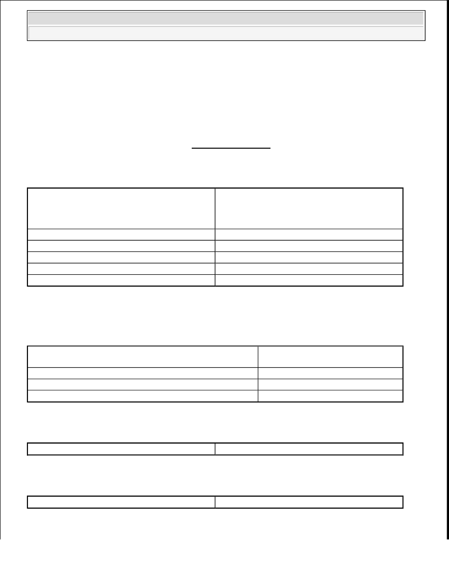
TYPICAL MALFUNCTION THRESHOLDS
Related DTCs
P0982: Shift solenoid valve S4/Range check (Low
resistance)
P0983: Shift solenoid valve S4/Range check (High
resistance)
Required sensors/Components
Shift solenoid valve S4
Frequency of operation
Continuous
Duration
0.128 sec. or more
MIL operation
Immediately
Sequence of operation
None
The monitor will run whenever the following DTCs are not
present
None
Battery voltage
8 V or higher
Ignition switch
ON
Starter
OFF
Shift solenoid valve S4
ON
Shift solenoid valve S4
OFF
2009 Toyota Tundra
2009 TRANSMISSION AB60F Automatic Transaxle - Tundra