Content .. 2807 2808 2809 2810 ..
Toyota Tundra. Manual - part 2809
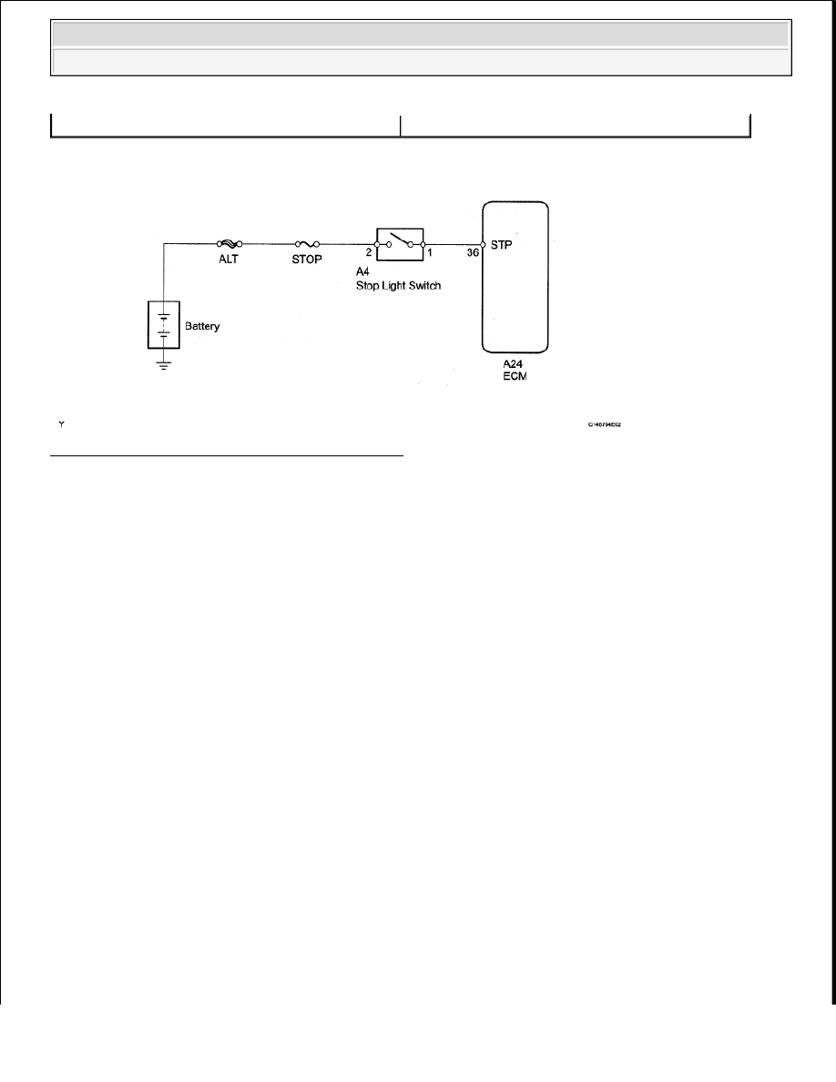
WIRING DIAGRAM
Fig. 46: Identifying Brake Switch Wiring Diagram
Courtesy of TOYOTA MOTOR SALES, U.S.A., INC.
INSPECTION PROCEDURE
1. DATA LIST
HINT:
Using the Techstream to read the Data List allows the values or states of switches, sensors, actuators and
other items to be read without removing any parts. This non-intrusive inspection can be very useful
because intermittent conditions or signals may be discovered before parts or wiring is disturbed. Reading
the Data List information early in troubleshooting is one way to save diagnostic time.
a. Warm up the engine.
b. Turn the ignition switch off.
c. Connect the Techstream to the DLC3.
d. Turn the ignition switch to ON.
e. Turn the Techstream on.
f. Enter the following menus: Powertrain/Engine and ECT/Data List.
g. According to the display on the Techstream, read the Data List.
Engine and ECT:
Stop light switch status
Stuck on
NOTE:
In the table below, the values listed under "Normal Condition" are
reference values. Do not depend solely on these reference values when
deciding whether a part is faulty or not.
2009 Toyota Tundra
2009 TRANSMISSION AB60F Automatic Transaxle - Tundra