Toyota Tundra. Manual - part 2775


  Index      Toyota     Toyota Tundra (2007-2010 year) - Service and Repair Manual


Search            copyright infringement  


Content   ..  2773  2774  2775  2776   ..


Toyota Tundra. Manual - part 2775


DESCRIPTION 

Speed signals are input into the tire pressure warning ECU from the combination meter. At the same time, the 
G-SW in the tire pressure warning valve and transmitter detects driving conditions, and sends signals to the tire 
pressure warning ECU. If the speed signal from the combination meter stops and the G-SW signal in the tire 
pressure warning valve and transmitter indicates that the vehicle is being driven, DTC C2174/74 is stored. 

DTC C2191/91 is stored only during the signal check. 

DTC DETECTION CONDITION TABLE 

WIRING DIAGRAM 

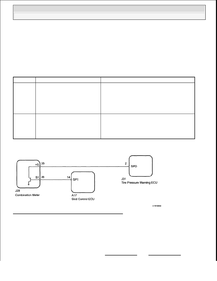
Fig. 28: Vehicle Speed Signal Malfunction - Wiring Diagram 
Courtesy of TOYOTA MOTOR SALES, U.S.A., INC. 

INSPECTION PROCEDURE 

DTC Code

Detection Condition

Trouble Area

C2174/74 Vehicle speed signal malfunction

Combination meter  

Vehicle speed signal circuit  

Harness or connector  

Tire pressure warning ECU  

Tire pressure warning valve and transmitter  

C2191/91 Test mode procedure is performed

Meter/gauge system (speed signal)  

Vehicle speed signal circuit  

Harness or connector  

Tire pressure warning ECU  

NOTE:

When replacing the tire pressure warning ECU, read the transmitter IDs 
stored in the old ECU using the Techstream and write them down before 
removal.  

It is necessary to perform INITIALIZATION after REGISTRATION of the 


2009 Toyota Tundra 

2009 SUSPENSION Tire & Wheel - Tundra


HINT: 

When the speedometer needle is not moving, first troubleshoot the meter/gauge system (See HOW TO 
PROCEED WITH TROUBLESHOOTING
 ). 

1. READ VALUE USING DATA LIST (VEHICLE SPEED) 

a. Turn the ignition switch off.  

b. Connect the Techstream to the DLC3.  

c. Turn the ignition switch to ON and the Techstream on.  

d. Enter the following menus: Chassis/Tire Pressure Monitor/Data List.  

e. Check that the values indicated on the Techstream and on the combination meter are the same. 

Tire Pressure Monitor  

TIRE PRESSURE MONITOR TABLE 

OK: Vehicle speed indicated on the Techstream indicates the actual speed.  

NG: Go to step 3 

OK: Go to next step  

2. CHECK DTC 

a. Perform a driving test.  

b. Check for DTCs. 

HINT: 

The time required for DTC C2174 to be stored is 20 minutes. 

Result  

RESULT TABLE 

transmitter IDs into the tire pressure warning ECU after the ECU and/or tire 
pressure warning valve and transmitter has been replaced.  

Tester 

Display

Measurement 

Item/Range

Normal Condition

Diagnostic Note

Vehicle 

Speed

Vehicle speed/ 
min.: 0 km/h (0 mph) 
max.: 255 km/h (158 
mph)

Almost same as actual 
vehicle speed

Speed indicated on 
combination meter

Result

Proceed to

DTC C2174 is not output

A


2009 Toyota Tundra 

2009 SUSPENSION Tire & Wheel - Tundra


B: Go to step 6 

A: USE SIMULATION METHOD TO CHECK (See HOW TO PROCEED WITH 
TROUBLESHOOTING
 ) 

3. CHECK HARNESS AND CONNECTOR (ECU - COMBINATION METER) 

a. Disconnect the J31 tire pressure warning ECU connector.  

b. Disconnect the J28 meter connector.  

c. Measure the resistance according to the value(s) in the table below. 

Standard Resistance  

TESTER CONNECTION SPECIFIED CONDITION TABLE 

Fig. 29: Identifying J31 Tire Pressure Warning ECU Connector & J28 Meter Connector 
Courtesy of TOYOTA MOTOR SALES, U.S.A., INC. 

NG: REPAIR OR REPLACE HARNESS OR CONNECTOR  

OK: Go to next step  

DTC C2174 is output

B

Tester Connection

Condition Specified Condition

J31-2 (SPD) - J28-35 (+S)

Always

Below 1 ohms

J31-2 (SPD) - Body ground Always

10 kohms or higher


2009 Toyota Tundra 

2009 SUSPENSION Tire & Wheel - Tundra


4. CHECK HARNESS AND CONNECTOR (COMBINATION METER - SKID CONTROL ECU) 

Fig. 30: Identifying Combination Meter Connector J28 & Skid Control ECU Connector Terminals 
A17
 
Courtesy of TOYOTA MOTOR SALES, U.S.A., INC. 

a. Disconnect the A17 skid control ECU connector.  

b. Disconnect the J28 meter connector.  

c. Measure the resistance according to the value(s) in the table below. 

Standard Resistance  

TESTER CONNECTION SPECIFIED CONDITION TABLE 

NG: REPAIR OR REPLACE HARNESS OR CONNECTOR  

OK: Go to next step  

5. CHECK DTC (SFI SYSTEM) 

a. Check for DTCs. 

HINT: 

for 1GR-FE (See DTC CHECK/CLEAR ).  

for 2UZ-FE (See DTC CHECK/CLEAR ).  

for 3UR-FE (See DTC CHECK/CLEAR ). 

Result  

Tester Connection

Condition Specified Condition

A17-14 (SP1) - J28-36 (S1)

Always

Below 1 ohms

A17-14 (SP1) - Body ground Always

10 kohms or higher


2009 Toyota Tundra 

2009 SUSPENSION Tire & Wheel - Tundra


Content   ..  2773  2774  2775  2776   ..