Content .. 2625 2626 2627 2628 ..
Toyota Tundra. Manual - part 2627
read.
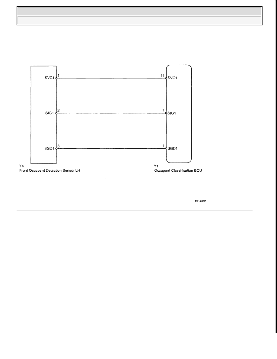
WIRING DIAGRAM
Fig. 207: Identifying Front Occupant Classification Sensor LH Circuit Malfunction - Wiring Diagram
Courtesy of TOYOTA MOTOR SALES, U.S.A., INC.
INSPECTION PROCEDURE
HINT:
If troubleshooting (wire harness inspection) is difficult to perform, remove the front seat RH installation
bolts to see the undersurface of the seat cushion.
In the above case, hold the seat so that it does not fall down. Holding the seat for a long period of time
may cause problems, such as seat rail deformation. Hold the seat up only for as long as necessary.
1. CHECK FOR DTC
a. Turn the ignition switch ON, and wait for at least 60 seconds.
NOTE:
After the ignition switch is turned OFF, the navigation system requires
approximately 90 seconds to record various types of memory and settings. As a
result, after turning the ignition switch OFF, wait 90 seconds or more before
disconnecting the cable from the negative (-) battery terminal.
2009 Toyota Tundra
2009 RESTRAINTS Supplemental Restraint System - Tundra