Toyota Tundra. Manual - part 2617


  Index      Toyota     Toyota Tundra (2007-2010 year) - Service and Repair Manual


Search            copyright infringement  


Content   ..  2615  2616  2617  2618   ..


Toyota Tundra. Manual - part 2617


b. Connect the negative (-) terminal cable to the battery, and wait for at least 2 seconds.  

c. Turn the ignition switch ON, and wait for at least 60 seconds.  

d. Clear the DTCs stored in the memory (see DTC CHECK/CLEAR ).  

e. Turn the ignition switch OFF.  

f. Turn the ignition switch ON, and wait for at least 60 seconds.  

g. Check the DTCs (see DTC CHECK/CLEAR ). 

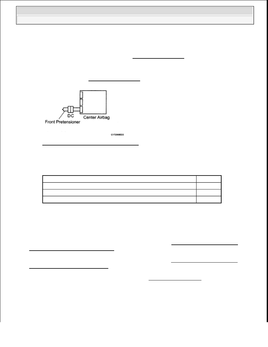
Fig. 187: Identifying Center Airbag Sensor 
Courtesy of TOYOTA MOTOR SALES, U.S.A., INC. 

Result  

RESULT TABLE 

HINT: 

Codes other than DTC B1905, B1906, B1907, B1908 maybe output at this time, but they are not 
related to this check. 

A: REPLACE CENTER AIRBAG SENSOR ASSEMBLY (See CENTER AIRBAG SENSOR 
ASSEMBLY (for Column Shift Type)
 ) 

B: REPLACE CENTER AIRBAG SENSOR ASSEMBLY (See CENTER AIRBAG SENSOR 
ASSEMBLY (for Floor Shift Type)
 ) 

C: USE SIMULATION METHOD TO CHECK (See DIAGNOSIS SYSTEM ) 

SRS WARNING LIGHT REMAINS ON 

DESCRIPTION 

The SRS warning light is located on the combination meter. 

Result

Proceed to

DTC B1905, B1906, B1907 or B1908 is output (for Column Shift Type)

A

DTC B1905, B1906, B1907 or B1908 is output (for Floor Shift Type)

B

DTC B1905, B1906, B1907 or B1908 is not output

C


2009 Toyota Tundra 

2009 RESTRAINTS Supplemental Restraint System - Tundra


When the SRS is normal, the SRS warning light comes on for approximately 6 seconds after the ignition switch 
is turned from OFF to ON, and then goes off automatically. 

If there is a malfunction in the SRS, the SRS warning light comes on to inform the driver of a problem. 

When terminals TC and CG of the DLC3 are connected, the DTC is displayed by blinking of the SRS warning 
light. 

The SRS is equipped with a voltage-increase circuit (DC-DC converter) in the center airbag sensor in case the 
source voltage drops. 

When the battery voltage drops, the voltage-increase circuit (DC-DC converter) functions to increase the 
voltage of the SRS to normal voltage. 

A malfunction in this circuit is not recorded in the center airbag sensor. The SRS warning light automatically 
goes off when the source voltage returns to normal. 

The signal to illuminate the SRS warning light is transmitted from the center airbag sensor to the combination 
meter through the CAN communication system. 

WIRING DIAGRAM 


2009 Toyota Tundra 

2009 RESTRAINTS Supplemental Restraint System - Tundra


Fig. 188: Identifying SRS Warning Light Remains ON Wiring Diagram 
Courtesy of TOYOTA MOTOR SALES, U.S.A., INC. 

INSPECTION PROCEDURE 

1. CHECK CAN COMMUNICATION SYSTEM 

a. Check if a CAN communication DTC is output (see DIAGNOSTIC TROUBLE CODE 

TABLE ). 

Result  

NOTE:

When disconnecting the cable from the negative (-) battery terminal while 
performing repairs, some systems need to be initialized after the cable is 
reconnected (see INITIALIZATION ).  

After the ignition switch is turned OFF, the navigation system requires 
approximately 90 seconds to record various types of memory and 
settings. As a result, after turning the ignition switch OFF, wait 90 seconds 
or more before disconnecting the cable from the negative (-) battery 
terminal.  


2009 Toyota Tundra 

2009 RESTRAINTS Supplemental Restraint System - Tundra


RESULT TABLE 

B: REPAIR CIRCUITS INDICATED BY OUTPUT DTCS  

A: Go to next step  

2. CHECK BATTERY 

a. Measure the voltage of the battery. 

Standard voltage:  

11 to 14 V  

NG: CHECK AND REPLACE BATTERY OR CHARGING SYSTEM  

OK: Go to next step  

3. CHECK CONNECTORS 

a. Turn the ignition switch OFF.  

b. Disconnect the negative (-) terminal cable from the battery, and wait for at least 90 seconds.  

c. Check that the connectors are properly connected to the center airbag sensor and combination 

meter. 

OK: The connectors are properly connected.  

NG: CONNECT CONNECTORS PROPERLY  

OK: Go to next step  

4. CHECK HARNESS AND CONNECTOR (SOURCE VOLTAGE OF CENTER AIRBAG 

SENSOR) 

a. Disconnect the J46 center airbag sensor connector.  

b. Connect the negative (-) terminal cable to the battery, and wait for at least 2 seconds.  

c. Turn the ignition switch ON.  

d. Operate all components of the electrical system (defogger, wipers, headlights, heater blower, etc.).  

e. Measure the voltage according to the value(s) in the table below. 

Standard voltage  

TESTER CONNECTION SPECIFIED CONDITION TABLE 

Result

Proceed to

DTC is not output

A

DTC is output

B

Tester Connection

Switch Condition Specified Condition


2009 Toyota Tundra 

2009 RESTRAINTS Supplemental Restraint System - Tundra


Content   ..  2615  2616  2617  2618   ..