Content .. 2401 2402 2403 2404 ..
Toyota Tundra. Manual - part 2403
c. Measure the resistance according to the value(s) in the table below.
Standard Resistance
TESTER CONNECTION SPECIFIED CONDITION CHART
NG: REPAIR OR REPLACE HARNESS OR CONNECTOR
OK: Go to Next Step
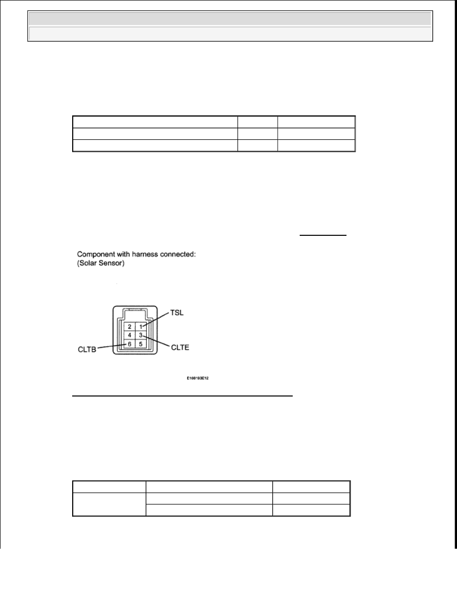
4. CHECK AUTOMATIC LIGHT CONTROL SENSOR (SOLAR SENSOR (TSL - CLTE
VOLTAGE))
a. Remove the solar sensor with its connector still connected (see REMOVAL ).
Fig. 56: Identifying Terminals Of Solar Sensor Connector
Courtesy of TOYOTA MOTOR SALES, U.S.A., INC.
b. Apply battery voltage between terminals 6 (CLTB) and 3 (CLTE) of the solar sensor.
c. Measure the voltage according to the value(s) in the table below.
Standard Voltage
TESTER CONNECTION SPECIFIED CONDITION CHART
HINT:
Tester Connection
Condition Specified Condition
J19-33 (TSD) - K19-1 (TSL)
Always
Below 1 ohms
J19-33 (TSD) or K19-1 (TSL) - Body ground Always
10 kohms or higher
Tester Connection
Condition
Specified Condition
1 (TSL) - 3 (CLTE)
Sensor is subjected to electric light
0.8 to 4.3 V
Sensor is covered with a cloth
Below 0.8 V
2009 Toyota Tundra
2009 HVAC Air Conditioning - Tundra