Toyota Tundra. Manual - part 2398


  Index      Toyota     Toyota Tundra (2007-2010 year) - Service and Repair Manual


Search            copyright infringement  


Content   ..  2396  2397  2398  2399   ..


Toyota Tundra. Manual - part 2398


DATA LIST 

OK:  

The display is as specified in the normal condition.  

Result  

RESULT REFERENCE 

B: PROCEED TO NEXT CIRCUIT INSPECTION SHOWN IN PROBLEM SYMPTOMS 
TABLE
 (See PROBLEM SYMPTOMS TABLE ) 

C: REPLACE AIR CONDITIONING AMPLIFIER (See REMOVAL ) 

A: Go to Next Step  

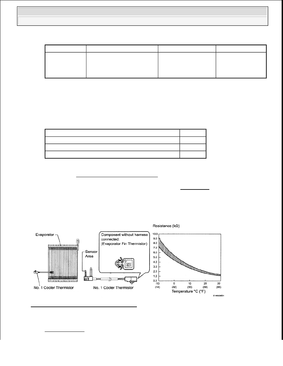
2. INSPECT NO. 1 COOLER THERMISTOR (EVAPORATOR FIN THERMISTOR) 

Fig. 36: Temperature And Resistance Graph 
Courtesy of TOYOTA MOTOR SALES, U.S.A., INC. 

a. Remove the No. 1 cooler thermistor (evaporator temperature sensor) connector (see 

DISASSEMBLY ).  

Tester Display

Measurement Item/Range

Normal Condition

Diagnostic Note

Evaporator Fin 

Thermistor

Evaporator fin 
thermistor/Min.:-29.7°C (-
21.46°F) 
Max.: 59.55°C (139.19°F)

Actual evaporator 
temperature is displayed

Open in circuit: -
29.7°C (-21.46°F) 
Short in circuit: 
59.55°C (139.19°F)

Result

Proceed to

NG

A

OK (Checking from the PROBLEM SYMPTOMS TABLE)

B

OK (Checking from the DTC)

C


2009 Toyota Tundra 

2009 HVAC Air Conditioning - Tundra


b. Measure the resistance according to the value(s) in the table below. 

Standard Resistance  

TESTER CONNECTION SPECIFIED CONDITION CHART 

HINT: 

As the temperature increases, the resistance decreases (see the graph ). 

NG: REPLACE NO. 1 COOLER THERMISTOR (EVAPORATOR FIN THERMISTOR) 
(See DISASSEMBLY ) 

OK: Go to Next Step  

3. REPAIR OR REPLACE AIR CONDITIONING HARNESS 

a. Repair or replace the air conditioning harness.  

4. CHECK FOR DTC 

a. Clear the DTC (see DTC CHECK/CLEAR ).  

b. Check for DTC (see DTC CHECK/CLEAR ). 

OK:  

DTC is not output.  

NG: REPLACE AIR CONDITIONING AMPLIFIER (See REMOVAL ) 

OK: END  

Tester Connection Condition Specified Condition

1 - 2

-10°C (14°F) 7.30 to 9.10 kohms

-5°C (23°F) 5.65 to 6.95 kohms

0°C (32°F)

4.40 to 5.35 kohms

5°C (41°F)

3.40 to 4.15 kohms

10°C (50°F) 2.70 to 3.25 kohms
15°C (59°F) 2.14 to 2.58 kohms
20°C (68°F) 1.71 to 2.05 kohms
25°C (77°F) 1.38 to 1.64 kohms
30°C (86°F) 1.11 to 1.32 kohms

NOTE:

Even slightly touching the sensor may change the resistance 
value. Be sure to hold the connector of the sensor.  

When measuring, the sensor temperature must be the same as 
the ambient temperature.  


2009 Toyota Tundra 

2009 HVAC Air Conditioning - Tundra


DTC B1421/21 SOLAR SENSOR CIRCUIT (PASSENGER SIDE) 

DESCRIPTION 

The solar sensor, which is installed on the upper side of the instrument panel, detects sunlight and controls the 
air conditioning in AUTO mode. The output current from the solar sensor varies according to the amount of 
sunlight. When the sunlight increases, the output current increases. As the sunlight decreases, the output current 
decreases. The air conditioning amplifier detects output current from the solar sensor. 

Fig. 37: Solar Sensor Output Voltage Graph 
Courtesy of TOYOTA MOTOR SALES, U.S.A., INC. 

DTC DETECTION CONDITION CHART 

WIRING DIAGRAM 

DTC

DTC Detection Condition

Trouble Area

B1421/21

Open or short in passenger side 
solar sensor circuit

Automatic light control 
sensor (solar sensor)  

Harness and connector 
between solar sensor and air 
conditioning amplifier  

Harness and connector 
between solar sensor and 
main body ECU  

Main body ECU  

Air conditioning amplifier  


2009 Toyota Tundra 

2009 HVAC Air Conditioning - Tundra


Fig. 38: Solar Sensor - Wiring Diagram 
Courtesy of TOYOTA MOTOR SALES, U.S.A., INC. 

INSPECTION PROCEDURE 

HINT: 

If DTC B1244 is output at the same time, troubleshoot DTC B1244 first (see DTC B1244 LIGHT SENSOR 
CIRCUIT MALFUNCTION
 ). 

1. READ VALUE USING TECHSTREAM (SOLAR SENSOR (for Passenger Side)) 

a. Use the Data List to check if the passenger side solar sensor is functioning properly. 

Air Conditioner  

DATA LIST 

OK:  

The display is as specified in the normal condition.  

Result  

RESULT REFERENCE 

Tester 

Display

Measurement 

Item/Range

Normal Condition

Diagnostic 

Note

Solar Sensor 

(P Side)

Passenger side solar 
sensor/Min.: 0 
Max.: 255

Passenger side solar sensor voltage 
increases as brightness increases

Open in circuit: 

Short in circuit: 
255


2009 Toyota Tundra 

2009 HVAC Air Conditioning - Tundra


Content   ..  2396  2397  2398  2399   ..