Toyota Tundra. Manual - part 2082


  Index      Toyota     Toyota Tundra (2007-2010 year) - Service and Repair Manual


Search            copyright infringement  


Content   ..  2080  2081  2082  2083   ..


Toyota Tundra. Manual - part 2082


3

REMOVE NO. 1 ENGINE UNDER COVER (See REMOVAL )  

4

DRAIN ENGINE COOLANT (See REPLACEMENT )  

5

REMOVE FRONT WIPER MOTOR AND LINK ASSEMBLY 

a

Remove the front wiper motor and link (see REMOVAL )   

6

REMOVE FRONT COWL TOP OUTER PANEL SUB-ASSEMBLY (See REMOVAL )  

7

REMOVE V-BANK COVER (See REMOVAL )  

8

REMOVE AIR CLEANER HOSE (See REMOVAL )  

9

REMOVE AIR CLEANER ASSEMBLY WITH ELEMENT (See REMOVAL )  

10

REMOVE INTAKE AIR SURGE TANK (See REMOVAL )  

11

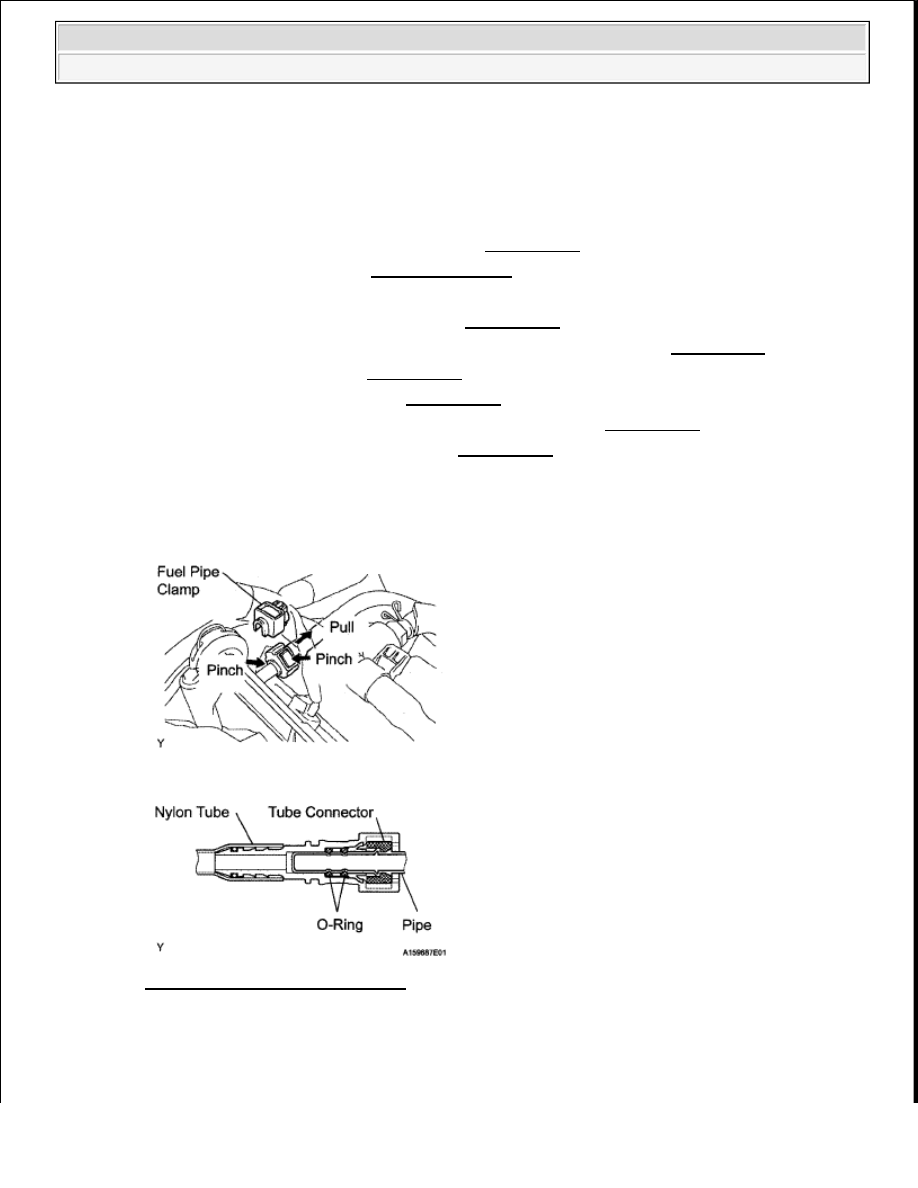
DISCONNECT NO. 1 FUEL PIPE SUB-ASSEMBLY 

a

Remove the fuel pipe clamp   

b

Pinch the tube connector, and then pull the fuel pipe out of the pipe as shown in the illustration  

Fig. 24: Pinching Tube Connector 
Courtesy of TOYOTA MOTOR SALES, U.S.A., INC. 

requires approximately 90 seconds to record various types of 
memory and settings. As a result, after turning the ignition switch 
OFF, wait 90 seconds or more before disconnecting the cable from 
the negative (-) battery terminal.  

NOTE:

Remove any dirt and foreign objects from the fuel tube 
connector before performing this work.  


2009 Toyota Tundra 

2009 ENGINE Fuel (1GR-FE) - Tundra


12

DISCONNECT NO. 2 FUEL PIPE SUB-ASSEMBLY 

a

Remove the fuel pipe clamp   

b

Pinch the tube connector, and then pull the fuel pipe out of the pipe as shown in the illustration  

Fig. 25: Pinching Tube Connector 
Courtesy of TOYOTA MOTOR SALES, U.S.A., INC. 

Do not allow any scratches or foreign objects on the parts when 
disconnecting, as the fuel tube connector has the O-ring that 
seals the pipe.  

Perform this work by hand. Do not use any tools.  

Do not forcibly bend, twist or turn the nylon tube.  

Keep the plug free from foreign objects.  

Protect the disconnected part by covering it with a plastic bag 
after disconnecting the fuel tube.  

If the fuel tube connector and pipe are stuck, push and pull to 
release them.  

NOTE:

Remove any dirt and foreign objects from the fuel tube 
connector before performing this work.  

Do not allow any scratches or foreign objects on the parts when 
disconnecting, as the fuel tube connector has the O-ring that 
seals the pipe.  

Perform this work by hand. Do not use any tools.  


2009 Toyota Tundra 

2009 ENGINE Fuel (1GR-FE) - Tundra


13

REMOVE FUEL DELIVERY PIPE SUB-ASSEMBLY 

a

Disconnect the 6 fuel injector connectors  

Fig. 26: Identifying Fuel Injector Connectors And Bolts 
Courtesy of TOYOTA MOTOR SALES, U.S.A., INC. 

b

Remove the 6 bolts and fuel delivery pipe together with the 6 fuel injectors  

14

REMOVE FUEL INJECTOR 

a

Pull the 6 fuel injectors from the fuel delivery pipe  

Fig. 27: Identifying Fuel Injectors From Fuel Delivery Pipe 
Courtesy of TOYOTA MOTOR SALES, U.S.A., INC. 

b

Remove the O-ring and injector vibration insulator from each fuel injector   

Do not forcibly bend, twist or turn the nylon tube.  

Keep the plug free from foreign objects.  

Protect the disconnected part by covering it with a plastic bag 
after disconnecting the fuel tube.  

If the fuel tube connector and pipe are stuck, push and pull to 
release them.  

NOTE:

Be careful not to drop the injectors when removing the fuel delivery 
pipe.


2009 Toyota Tundra 

2009 ENGINE Fuel (1GR-FE) - Tundra


INSPECTION 

1

INSPECT INJECTOR ASSEMBLY 

a

Measure the resistance according to the value(s) in the table below  

Standard resistance  

INJECTOR ASSEMBLY TESTER CONNECTION SPECIFIED CONDITION CHART 

Fig. 28: Measuring Resistance Between Injector Assembly 
Courtesy of TOYOTA MOTOR SALES, U.S.A., INC. 

If the result is not as specified, replace the injector assembly  

2

INSPECT INJECTION VOLUME AND LEAKAGE 

a

Check the injector injection  

1

Assemble SST as shown in the illustration  

SST 09268-31011 (90467-13001, 09268-41091, 09268-41120, 09268-41500, 95333-06030, 
95336-08070), 09268-41140, 09268-41400
  

Tester Connection Condition Specified Condition

1 - 2

20°C (68°F) 11 6 to 12 4 ohms

CAUTION:

This test involves high-pressure fuel and electricity.  

Take every precaution regarding safe handling of both the 
fuel and the electrical parts.  

Perform this test in a safe area, and avoid any sparks or 
flame.  

Do not smoke.  


2009 Toyota Tundra 

2009 ENGINE Fuel (1GR-FE) - Tundra


Content   ..  2080  2081  2082  2083   ..