Toyota Tundra. Manual - part 204


  Index      Toyota     Toyota Tundra (2007-2010 year) - Service and Repair Manual


Search            copyright infringement  


Content   ..  202  203  204  205   ..


Toyota Tundra. Manual - part 204


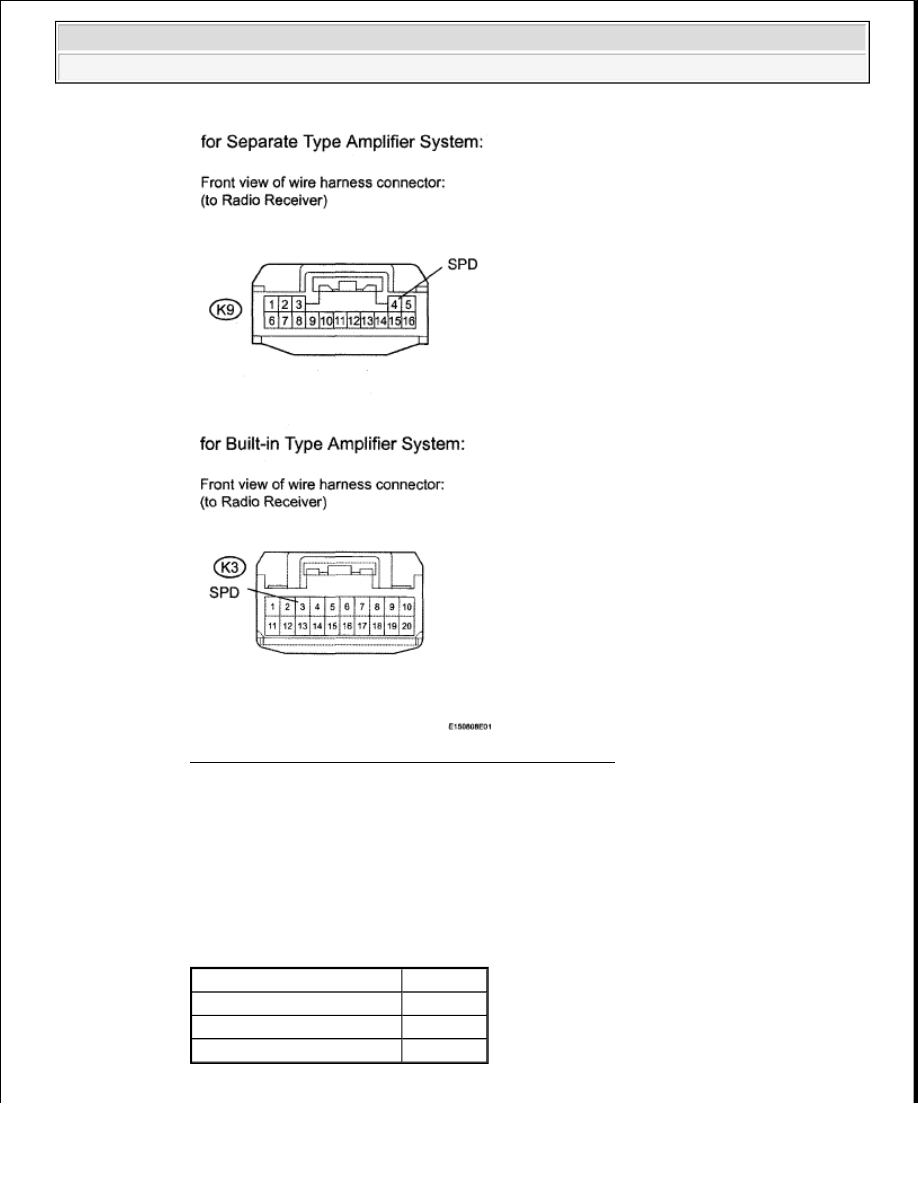
Fig. 183: Identifying K9 And K3 Connectors Terminals 
Courtesy of TOYOTA MOTOR SALES, U.S.A., INC. 

4. Measure the voltage between terminal SPD of the wire harness connector and body ground 

when the drive wheels are turned slowly. 

OK: Voltage pulses as shown in the illustration.  

Result:  

RESULT REFERENCE 

Result

Proceed to

NG

A

OK (for Column Shift Type)

B

OK (for Floor Shift Type)

C


2009 Toyota Tundra 

2009 ACCESSORIES AND EQUIPMENT Audio/Visual - Tundra


B: REPLACE RADIO RECEIVER (see REMOVAL ) 

C: REPLACE RADIO RECEIVER (see REMOVAL ) 

Fig. 184: Voltage Pulses Pattern 
Courtesy of TOYOTA MOTOR SALES, U.S.A., INC. 

A: Go to next step.  

3. CHECK HARNESS AND CONNECTOR (COMBINATION METER - RADIO RECEIVER) 

a. Disconnect the K3*1 or K9*2 receiver connector. 

HINT: 

*1: for Built-in Type Amplifier System  

*2: for Separate Type Amplifier System  

b. Disconnect the J28 meter connector.  

c. Measure the resistance according to the value(s) in the table below. 

Standard resistance:  

for Separate Type Amplifier System  

TESTER CONNECTION SPECIFIED CONDITION 

for Built-in Type Amplifier System  

TESTER CONNECTION SPECIFIED CONDITION 

Tester Connection

Condition Specified Condition

K9-4 (SPD) - J28-35 (+S)

Always

Below 1 ohms

K9-4 (SPD) - Body ground

10 kohms or higher

Tester Connection

Condition Specified Condition

K3-3 (SPD) - J28-35 (+S)

Always

Below 1 ohms

K3-3 (SPD) - Body ground

10 kohms or higher


2009 Toyota Tundra 

2009 ACCESSORIES AND EQUIPMENT Audio/Visual - Tundra


NG: REPAIR OR REPLACE HARNESS OR CONNECTOR  

Fig. 185: Checking Harness And Connector (Combination Meter - Radio Receiver) 
Courtesy of TOYOTA MOTOR SALES, U.S.A., INC. 

OK: REPLACE COMBINATION METER (See REMOVAL ) 

STEERING PAD SWITCH CIRCUIT 

DESCRIPTION 


2009 Toyota Tundra 

2009 ACCESSORIES AND EQUIPMENT Audio/Visual - Tundra


This circuit sends an operation signal from the steering pad switch to the radio receiver. If there is an open in 
the circuit, the audio system cannot be operated using the steering pad switch. If there is a short in the circuit, 
the same condition as when the switch is continuously depressed occurs. Therefore, the radio receiver cannot be 
operated using the steering pad switch, and also the radio receiver itself cannot function. 

WIRING DIAGRAM 

Fig. 186: Steering Pad Switch - Wiring Diagram 
Courtesy of TOYOTA MOTOR SALES, U.S.A., INC. 

INSPECTION PROCEDURE 

1. INSPECT RADIO RECEIVER 

a. Disconnect the K3 receiver connector.  

b. Measure the resistance according to the value(s) in the table below. 

Standard resistance  

CAUTION: The vehicle is equipped with an SRS (Supplemental Restraint System) 

which includes components such as airbags. Before servicing (including 
removal or installation of parts), be sure to read the precautionary notice 
for the SRS (see PRECAUTION ).


2009 Toyota Tundra 

2009 ACCESSORIES AND EQUIPMENT Audio/Visual - Tundra


Content   ..  202  203  204  205   ..