Toyota Tundra. Manual - part 1625


  Index      Toyota     Toyota Tundra (2007-2010 year) - Service and Repair Manual


Search            copyright infringement  


Content   ..  1623  1624  1625  1626   ..


Toyota Tundra. Manual - part 1625


b. Turn the ignition switch to ON.  

c. Turn the Techstream ON.  

d. Clear DTCs (see DTC CHECK/CLEAR ).  

e. Start the engine and wait for 10 minutes or more.  

f. Enter the following menus: Powertrain/Engine and ECT/Trouble Codes/Pending.  

g. If no pending DTC is displayed, the repair has been successfully completed. 

NEXT: END  

DTC P2A00 A/F SENSOR CIRCUIT SLOW RESPONSE (BANK 1 SENSOR 1); DTC P2A03 A/F 
SENSOR CIRCUIT SLOW RESPONSE (BANK 2 SENSOR 1) 

DESCRIPTION 

Refer to DTC P2195 . 

DTC DETECTION CONDITION AND TROUBLE AREA REFERENCE CHART 

MONITOR DESCRIPTION 

After the engine is warmed up, the ECM performs air-fuel ratio feedback control to maintain the air-fuel ratio at 
the stoichiometric level. In addition, active A/F control is performed for approximately 10 seconds after the 
preconditions are met in order to measure the A/F sensor response rate. During active A/F control, the ECM 
forcibly increases and decreases the injection volume a certain amount, based on the stoichiometric air-fuel ratio 
learned during normal air-fuel ratio control, and measures the A/F sensor response rate. The ECM receives a 
signal from the A/F sensor while performing active A/F control and uses it to calculate the A/F sensor response 
rate deterioration level. 

If the A/F sensor response rate deterioration level is less than the threshold, the ECM interprets this as a 
malfunction and stores the DTC. 
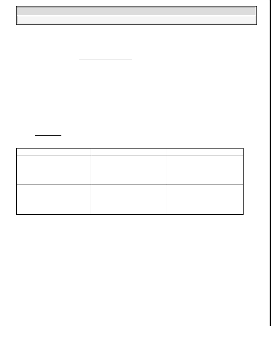
DTC

DTC Detection Condition

Trouble Area

P2A00

Calculated value of air-fuel ratio 
(A/F) sensor response rate 
deterioration level less than 
threshold (2 trip detection logic)

Open or short in A/F sensor 
circuit (for Bank 1)  

A/F sensor (for Bank 1)  

ECM  

P2A03

Calculated value of air-fuel ratio 
(A/F) sensor response rate 
deterioration level less than 
threshold (2 trip detection logic)

Open or short in A/F sensor 
circuit (for Bank 2)  

A/F sensor (for Bank 2)  

ECM  


2009 Toyota Tundra 

2009 ENGINE PERFORMANCE Engine Control System (3UR-FBE) - Tundra


Saturday, June 19, 2010 7:34:46 PM

Page 593 

© 2006 Mitchell Repair Information Company, LLC. 

Fig. 256: Air-Fuel Ratio Sensor Output 
Courtesy of TOYOTA MOTOR SALES, U.S.A., INC. 

CONFIRMATION DRIVING PATTERN 

HINT: 

This confirmation driving pattern is used in the "Perform Confirmation Driving Pattern" procedure of the 
following diagnostic troubleshooting procedure.  

Performing this confirmation driving pattern will activate the A/F sensor monitor. (The catalyst monitor 
is performed simultaneously.) This is very useful for verifying the completion of a repair. 

Fig. 257: Vehicle Driving Pattern 
Courtesy of TOYOTA MOTOR SALES, U.S.A., INC. 

1. Connect the Techstream to the DLC3.  

2. Clear the DTC (See DTC CHECK/CLEAR ). 

HINT: 

Even if no DTCs are stored, perform the DTC clear operation to start alcohol concentration learning. 

3. Start the engine. 

NOTE:

This test will not be completed if the vehicle is driven under absolutely 
constant speed conditions such as with cruise control activated.


2009 Toyota Tundra 

2009 ENGINE PERFORMANCE Engine Control System (3UR-FBE) - Tundra


Saturday, June 19, 2010 7:34:46 PM

Page 594 

© 2006 Mitchell Repair Information Company, LLC. 

HINT: 

After clearing the DTCs, the engine may become difficult to start if the concentration of alcohol in the 
fuel is high. Therefore, it may be necessary to crank the engine a few times before it starts. 

4. Warm up the engine until the engine coolant temperature is 75°C (167°F) or more [A].  

5. Drive the vehicle at 32 km/h (20 mph) or more and maintain a constant speed for 2 minutes or more [B].  

6. After this driving make sure that the Data List "Alcohol Density Learning" is "Compl".  

7. Drive the vehicle at between 60 and 120 km/h (40 and 75 mph) and maintain a constant speed for at least 

10 minutes [C]. 

8. Drive the vehicle at 60 km/h (40 mph) or more and decelerate the vehicle for 5 seconds or more. Perform 

this 3 times [D].  

9. Turn the Techstream on.  

10. Enter the following menus: Powertrain/Engine and ECT/Utility/All Readiness.  

11. Enter the following DTCs: P2195, P2196, P2197 and P2198.  

12. Check that the DTC monitor is NORMAL. If the DTC monitor is INCOMPLETE, perform the drive 

pattern increasing the vehicle speed and using the second gear to decelerate the vehicle [D].  

MONITOR STRATEGY 

MONITOR STRATEGY 

TYPICAL ENABLING CONDITIONS 

TYPICAL ENABLING CONDITIONS 

CAUTION: Perform this drive pattern on a level road as much as possible and 

strictly observe the posted speed limits and traffic laws while driving.

Related DTCs

P2A00: Air-Fuel Ratio (A/F) sensor slow response (Bank 1) 
P2A03: Air-Fuel Ratio (A/F) sensor slow response (Bank 2)

Required Sensors/Components (Main)

A/F sensor

Required Sensors/Components (Related)

Vehicle speed sensor, Crankshaft position sensor

Frequency of Operation

Once per driving cycle

Duration

10 to 15 seconds

MIL Operation

2 driving cycles

Sequence of Operation

None

P0016, P0018 (VVT System - Misalignment) 
P0017, P0019 (Exhaust VVT System - Misalignment) 
P0031, P0032, P0051, P0052 (Air Fuel Ratio Sensor Heater) 
P0102, P0103 (Mass Air Flow Sensor) 
P0112, P0113 (Intake Air Temperature Sensor) 
P0115, P0117, P0118 (Engine Coolant Temperature Sensor) 
P0125 (Insufficient Coolant Temperature for Closed Loop 


2009 Toyota Tundra 

2009 ENGINE PERFORMANCE Engine Control System (3UR-FBE) - Tundra


Saturday, June 19, 2010 7:34:46 PM

Page 595 

© 2006 Mitchell Repair Information Company, LLC. 

TYPICAL MALFUNCTION THRESHOLDS 

TYPICAL MALFUNCTION THRESHOLDS CONDITIONS 

MONITOR RESULT 

Refer to CHECKING MONITOR STATUS . 

WIRING DIAGRAM 

Refer to DTC P2195 . 

INSPECTION PROCEDURE 

HINT: 

Monitor runs whenever following DTCs 
not present

Fuel Control) 
P0120, P0121, P0122, P0123, P0220, P0222, P0223, P2135 
(Throttle Position Sensor) 
P0128 (Thermostat) 
P0171, P0172, P0174, P0175 (Fuel System) 
P0301 - P0308 (Misfire) 
P0335 (Crankshaft Position Sensor) P1340 (Camshaft Position 
Sensor) 
P0451, P0452, P0453 (EVAP System) 
P0412, P0415, P0418, P0419, P1613, P1614 (Secondary Air 
Injection System Control) 
P2440, P2441, P2442, P2443, P2444, P2445, P2446, P2447 
(Secondary Air Injection System) 
P0500, P0722 (Vehicle Speed Sensor) 
P0505 (IAC Valve)

Active A/F control

Performing

Active A/F control performed when 
following conditions met

-

Engine coolant temperature

75°C (167°F) or more

Battery voltage

11 V or more

Idle

OFF

Engine speed

Less than 4000 RPM

A/F sensor status

Activated

Fuel-cut

OFF

Engine load

10 to 70%

Shift position

2nd or more

Catalyst monitor

Not yet

Intake air amount

2.5 to 12g/sec.

Response rate deterioration level

Less than 0.2 V


2009 Toyota Tundra 

2009 ENGINE PERFORMANCE Engine Control System (3UR-FBE) - Tundra


Saturday, June 19, 2010 7:34:46 PM

Page 596 

© 2006 Mitchell Repair Information Company, LLC. 


Content   ..  1623  1624  1625  1626   ..