Toyota Tundra. Manual - part 1568


  Index      Toyota     Toyota Tundra (2007-2010 year) - Service and Repair Manual


Search            copyright infringement  


Content   ..  1566  1567  1568  1569   ..


Toyota Tundra. Manual - part 1568


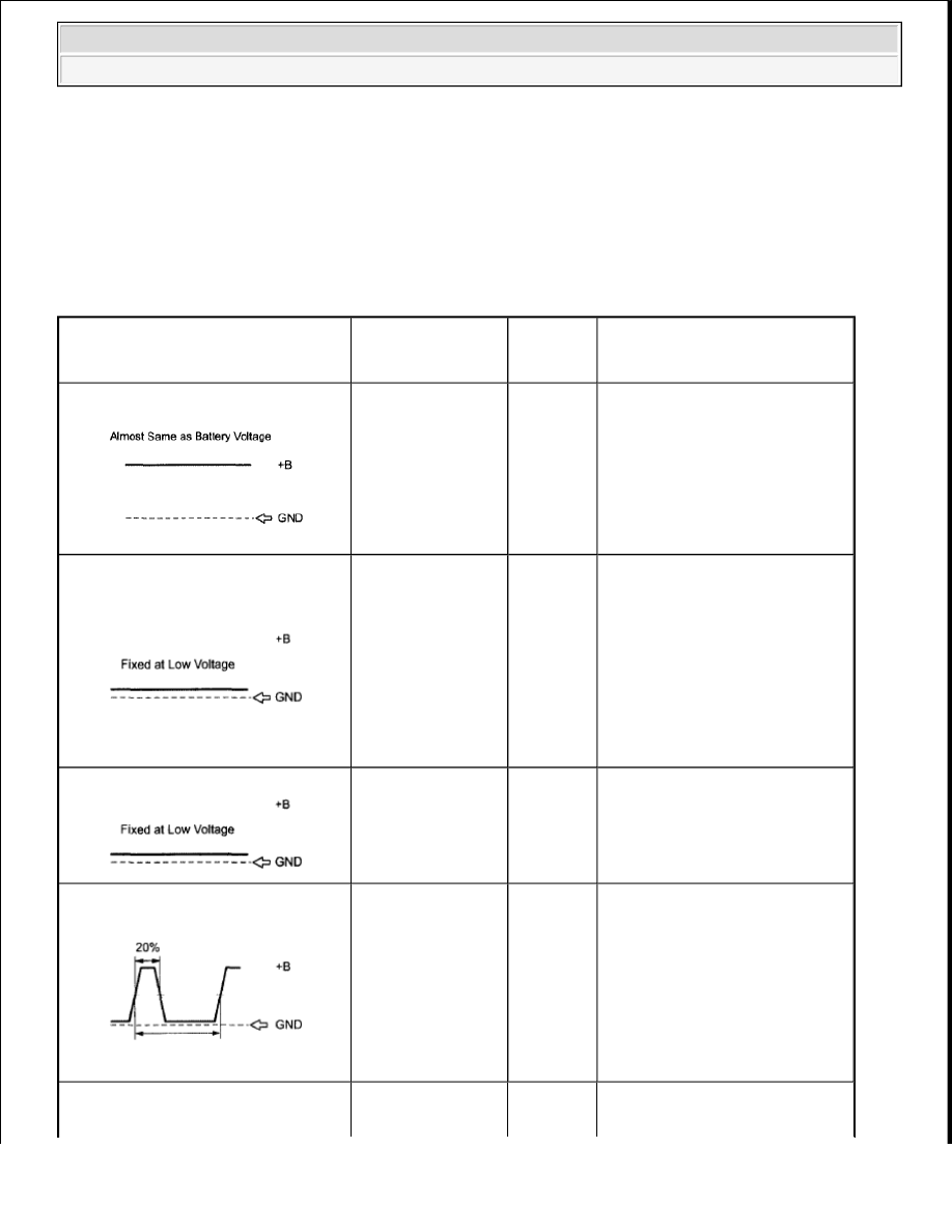
AID DIAGNOSTIC SIGNAL WAVEFORMS 

System Check operations to prevent the system from overheating.  

When performing the Air Injection Check operation after the battery cable 
has been reconnected, wait for 7 minutes with the ignition switch turned to 
ON or the engine running.  

Turn the ignition switch off when the Air Injection Check operation 
finishes.  

AID Diagnostic Signal Waveforms

ECM Commands

DTCs 

(ECM 

Output)

Suspected Trouble Areas

100% Duty 

Ratio

Any Secondary Air 

Injection (AIR) 

System operation

P1613 
P1614

Open in diagnostic signal 
circuit  

Air Injection Control 
Driver (AID)  

Open in AID BATT circuit 

Short between +B and 
diagnostic signal circuits  

0% Duty 

Ratio

AIR System: ON 

(Air pump ON, 

ASV ON)

P1613 
P1614

Open or short in air pump 
or Air Switching Valve 
(ASV) command signal 
circuit (ECM - AID)  

Short between diagnostic 
signal circuit and body 
ground  

AID  

ECM  

0% Duty 

Ratio

AIR System: OFF 

(Air pump OFF, 

ASV OFF)

-

Normal

20% Duty 

Ratio

Air Pump: ON

P0418 
P0419

Short between air pump 
drive circuit and body 
ground  

Harness and connector 
(AID - Pump)  

Air pump  

AID  

ECM  

20% Duty Ratio

Open in air pump drive 
circuit (AID - Pump)  


2009 Toyota Tundra 

2009 ENGINE PERFORMANCE Engine Control System (3UR-FBE) - Tundra


HINT: 

By using the Techstream to perform the Air Injection Check operation in the System Check, the air-fuel 
ratio and the pressure in the secondary air injection system passage can be checked while the secondary 
air injection system is operating. This helps technicians to troubleshoot the system when it malfunctions.  

Read freeze frame data using the Techstream. Freeze frame data records the engine condition when 

Ratio

Air Pump: OFF

P0418 
P0419

Harness and connector 
(AID - Pump)  

Air pump  

AID  

ECM  

40% Duty 

Ratio

ASV: ON

P0412 
P0415

Short between ASV drive 
circuit and body ground  

Harness and connector 
(AID - ASV)  

ASV  

AID  

ECM  

40% Duty 

Ratio

ASV: OFF

P0412 
P0415

Open in ASV drive circuit 
(AID - ASV)  

Harness and connector 
(AID - ASV)  

AID  

ASV  

ECM  

80% Duty 

Ratio

AIR System: OFF 

(Air pump OFF, 

ASV OFF)

P1613 
P1614

AID  

ECM  

80% Duty 

Ratio

AIR System: ON 

(Air pump ON, 

ASV ON)

-

Normal

Other than above (other than 0, 20, 
40, 80 and 100% duty)

-

P1613 
P1614

AID  

Open in AID ground 
circuit  


2009 Toyota Tundra 

2009 ENGINE PERFORMANCE Engine Control System (3UR-FBE) - Tundra


malfunctions are detected. When troubleshooting, freeze frame data can help determine if the vehicle was 
moving or stationary, if the engine was warmed up or not, if the air-fuel ratio was lean or rich, and other 
data from the time the malfunction occurred.  

1. INSPECT AIR PUMP ASSEMBLY 

a. Disconnect the D56 or D57 air pump connector. 

Fig. 163: Identifying Terminals Of D56 Or D57 Air Pump Connectors 
Courtesy of TOYOTA MOTOR SALES, U.S.A., INC. 

b. Measure the resistance according to the value(s) in the table below. 

Standard resistance  

RESISTANCE SPECIFIED CONDITION 

NG: REPLACE AIR PUMP ASSEMBLY (See REMOVAL ) 

OK: Go to Next Step  

2. CHECK HARNESS AND CONNECTOR (AIR PUMP - BODY GROUND) 

a. Disconnect the D56 or D57 air pump connector. 

Fig. 164: Identifying Terminals Of D56 Or D57 Air Pump Connector 

Tester Connection Condition Specified Condition

1 - 2

20°C (68°F)

0.44 to 1 ohms


2009 Toyota Tundra 

2009 ENGINE PERFORMANCE Engine Control System (3UR-FBE) - Tundra


Courtesy of TOYOTA MOTOR SALES, U.S.A., INC. 

b. Measure the resistance according to the value(s) in the table below. 

Standard resistance  

RESISTANCE SPECIFIED CONDITION 

NG: REPAIR OR REPLACE HARNESS OR CONNECTOR  

OK: Go to Next Step  

3. CHECK HARNESS AND CONNECTOR (AIR PUMP - AIR INJECTION CONTROL DRIVER) 

a. Disconnect the D56 or D57 air pump connector.  

b. Disconnect the D48 or D52 AID connector. 

Fig. 165: Identifying Terminals Of D48 Or D52 AID Connectors 
Courtesy of TOYOTA MOTOR SALES, U.S.A., INC. 

c. Measure the resistance according to the value(s) in the table below. 

Standard resistance  

RESISTANCE SPECIFIED CONDITION 

NG: REPAIR OR REPLACE HARNESS OR CONNECTOR  

OK: REPLACE AIR INJECTION CONTROL DRIVER (See REMOVAL ) 

Tester Connection Condition Specified Condition

D56-1 - Body ground Always

Below 1 ohms

D57-1 - Body ground Always

Below 1 ohms

Tester Connection

Condition Specified Condition

D56-2 - D48-2 (VP)

Always

Below 1 ohms

D57-2 - D52-2 (VP2)

Always

Below 1 ohms

D56-2 or D48-2 (VP) - Body ground

Always

10 kohms or higher

D57-2 or D52-2 (VP2) - Body ground Always

10 kohms or higher


2009 Toyota Tundra 

2009 ENGINE PERFORMANCE Engine Control System (3UR-FBE) - Tundra


Content   ..  1566  1567  1568  1569   ..