Toyota Tundra. Manual - part 1464


  Index      Toyota     Toyota Tundra (2007-2010 year) - Service and Repair Manual


Search            copyright infringement  


Content   ..  1462  1463  1464  1465   ..


Toyota Tundra. Manual - part 1464


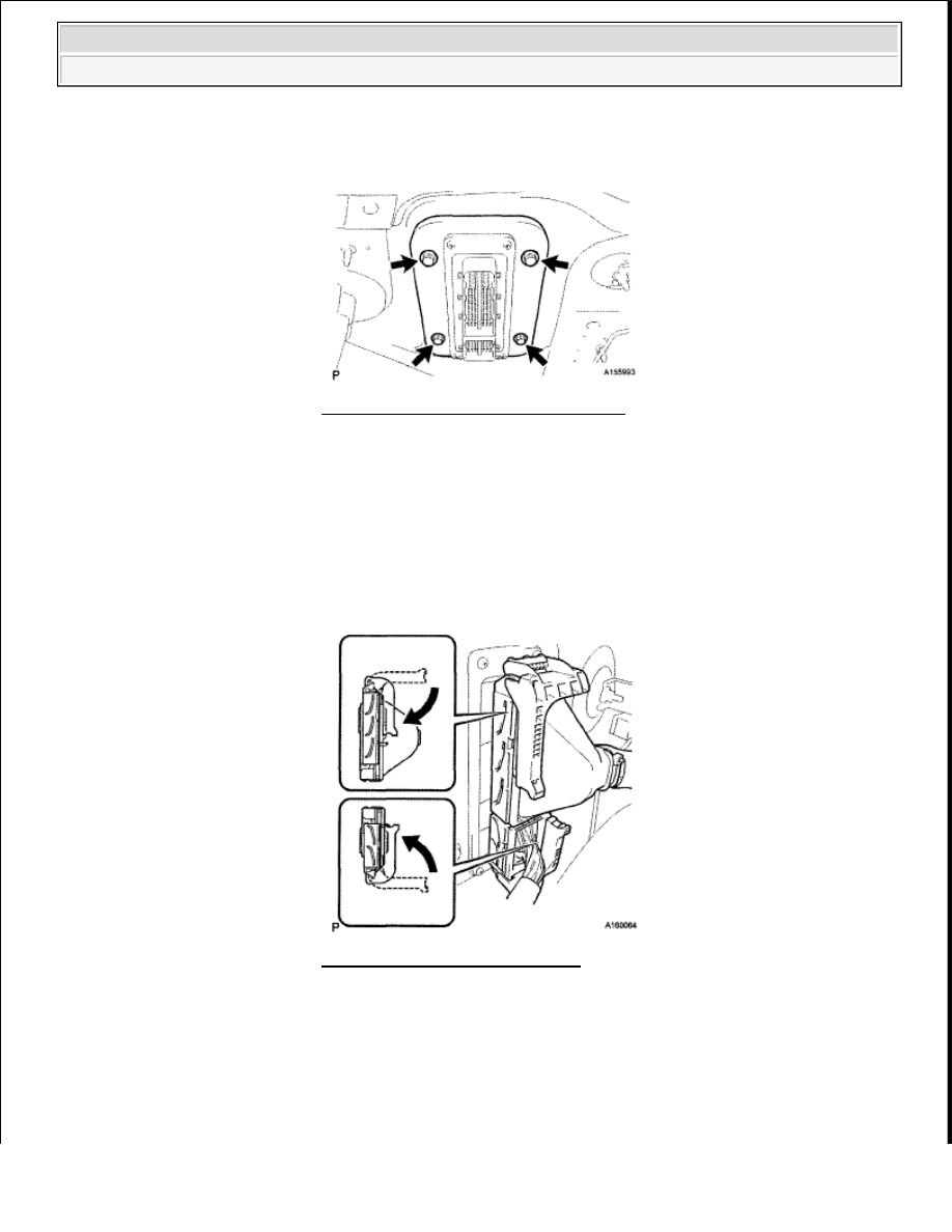
b. Connect the 2 ECM connectors and push each lock lever down to lock the ECM connectors. 

3. CONNECT CONNECTOR HOLDER BLOCK 

a. Install the connector holder block with the 3 bolts. 

Torque: 7.3 N*m (74 kgf*cm, 65 in.*lbf)  

4. CONNECT CABLE TO NEGATIVE BATTERY TERMINAL 

Do not damage the gasket. 

Fig. 343: Locating ECM With Bolts 

NOTE:

Make sure that the lock lever is raised 90° before connecting the 
ECM connectors. Failure to do this may cause the lock lever and 
terminals to break.  

Do not twist the wire harness when connecting the ECM 
connectors. 

Fig. 344: Pushing Lock Lever 


2008 Toyota Tundra 

2008 ENGINE PERFORMANCE Engine Control System (2UZ-FE) - Tundra


Fig. 345: Locating Connector Holder Block Bolts 

ACCELERATOR PEDAL 

COMPONENTS 

NOTE:

Some systems need to be initialized after the cable is reconnected. (See 
INITIALIZATION ).


2008 Toyota Tundra 

2008 ENGINE PERFORMANCE Engine Control System (2UZ-FE) - Tundra


Fig. 346: Identifying Accelerator Pedal Replacement Components With Torque Specification 

ON-VEHICLE INSPECTION 

1. INSPECT ACCELERATOR PEDAL ROD ASSEMBLY 

a. Connect the Techstream to the DLC3.  

b. Turn the ignition switch ON.  

c. Push the Techstream main switch ON.  

d. Enter the following menus: Powertrain/Engine and ECT/Data List/ETCS/Accelerator Position No. 

1 and Accelerator Position No. 2.  


2008 Toyota Tundra 

2008 ENGINE PERFORMANCE Engine Control System (2UZ-FE) - Tundra


e. Read the value displayed on the tester. 

ACCEL POS #1 (Accelerator Position No. 1)  

Standard voltage  

STANDARD VOLTAGE SPECIFICATION 

ACCEL POS #2 (Accelerator Position No. 2)  

Standard voltage  

STANDARD VOLTAGE SPECIFICATION 

If the result is not as specified, check the accelerator pedal, wire harness or ECM. 

REMOVAL 

1. DISCONNECT CABLE FROM NEGATIVE BATTERY TERMINAL 

2. REMOVE ACCELERATOR PEDAL ROD ASSEMBLY 

a. Disconnect the accelerator pedal position sensor connector.  

b. Remove the 2 nuts and accelerator pedal.  

INSTALLATION 

1. INSTALL ACCELERATOR PEDAL ROD ASSEMBLY 

Condition

Specified Condition

Accelerator pedal is released

0.5 to 1.1 V

Accelerator pedal is depressed

2.6 to 4.5 V

Condition

Specified Condition

Accelerator pedal is released

1.2 to 2.0 V

Accelerator pedal is depressed

3.4 to 5.0 V

NOTE:

Some systems need to be initialized after the cable is reconnected. 
(See INITIALIZATION ).  

After the ignition switch is turned OFF, the navigation system 
requires approximately 90 seconds to record various types of 
memory and settings. As a result, after turning the ignition switch 
OFF, wait 90 seconds or more before disconnecting the cable from 
the negative (-) battery terminal.  

NOTE:

Avoid physical shocks to the accelerator pedal assembly.  


2008 Toyota Tundra 

2008 ENGINE PERFORMANCE Engine Control System (2UZ-FE) - Tundra


Content   ..  1462  1463  1464  1465   ..