Toyota Tundra. Manual - part 1406


  Index      Toyota     Toyota Tundra (2007-2010 year) - Service and Repair Manual


Search            copyright infringement  


Content   ..  1404  1405  1406  1407   ..


Toyota Tundra. Manual - part 1406


properly. If outputs from the CPUs are different and deviate from the standards, the ECM will illuminate the 
MIL and set a DTC immediately. 

DTC DETECTION CONDITION AND TROUBLE AREA 

MONITOR STRATEGY 

MONITOR STRATEGY 

TYPICAL ENABLING CONDITIONS 

TYPICAL ENABLING CONDITIONS 

TYPICAL MALFUNCTION THRESHOLDS 

TYPICAL MALFUNCTION THRESHOLDS 

INSPECTION PROCEDURE 

1. CHECK DTC 

a. Clear DTC. (See DTC CHECK/CLEAR ).  

b. Turn the ignition switch off.  

c. Disconnect the cable from the negative battery terminal and wait for 1 minute.  

d. Connect the cable to the negative battery terminal.  

e. Turn the ignition switch to ON.  

f. Check DTC. 

OK: P1607 is not present.  
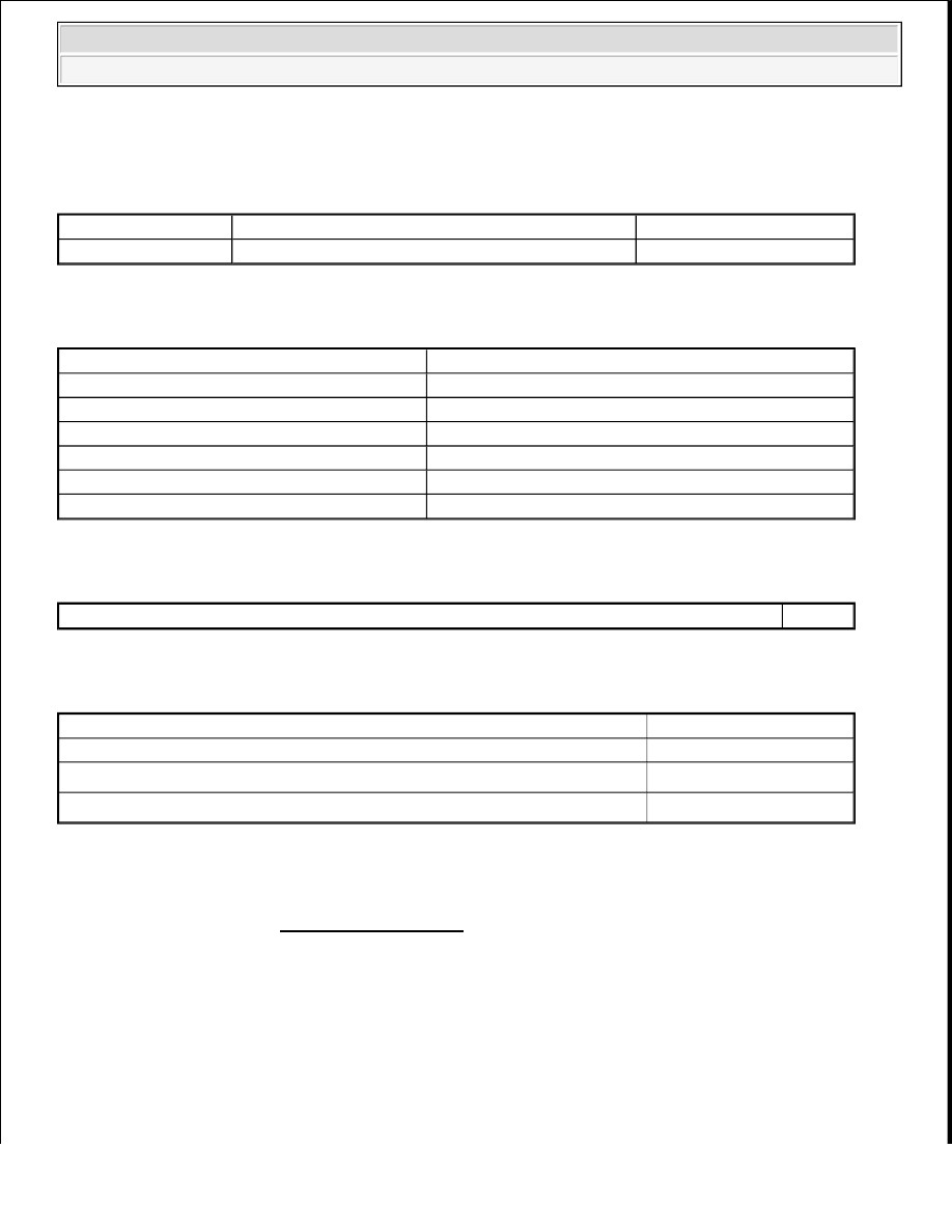
DTC Code

DTC Detection Condition

Trouble Area

P1607

ECM CPUs malfunction

ECM

Related DTC

P1607: Internal control module range check

Required sensors/Components (main)

ECM

Required sensors/Components (sub)

Cruise control

Frequency of Operation

Continuous

Duration

0.3 seconds

MIL Operation

Immediate

Sequence of Operation

None

Monitor runs whenever the following DTCs are not present

None

Cruise control

Forbiddance

When either condition below is met:

-

Cruise control  

Operating

Low speed control  

Operating


2008 Toyota Tundra 

2008 ENGINE PERFORMANCE Engine Control System (2UZ-FE) - Tundra


NG : REPLACE ECM (See REMOVAL ) 

OK : CHECK FOR INTERMITTENT PROBLEMS (See CHECK FOR INTERMITTENT 
PROBLEMS
 ) 

DTC P1613 SECONDARY AIR INJECTION DRIVER MALFUNCTION; DTC P1614 SECONDARY 
AIR INJECTION SYSTEM DRIVER BANK 2 

DESCRIPTION 

Refer to DTC P0412 . 

DTC DETECTION CONDITION AND TROUBLE AREA 

DTC 

Code

DTC Detection Condition

Trouble Area

P1613 
P1614

Either of following conditions (1) or (2) met: 

1. All of following conditions met (1 trip 

detection logic): 

Either of air pump or air switching 
valve not operating  

Diagnostic signal from Air Injection 
Control Driver (AID) 80%  

Battery voltage 8 V or higher  

2. Both of following conditions met (1 trip 

detection logic): 

Battery voltage 8 V or higher  

Diagnostic signal from AID abnormal 
(duty signal other than 0,20, 40, 80 
and 100%)  

AID  

Open in AID ground circuit  

P1613 
P1614

All of following conditions met (1 trip detection 
logic): 

a. Air injection system operating (Air 

Switching Valve [ASV] ON and air pump 
ON)  

b. Diagnostic signal from Air Injection 

Control Driver (AID) 0%  

c. Battery voltage 8 V or higher  

Short in diagnostic information signal 
circuit (AID - ECM)  

Open or short in air pump and air 
switching valve command signal 
circuit (AID - ECM)  

Open in AID ground circuit  

AID  

ECM  

P1613 
P1614

Both of following conditions met (1 trip detection 
logic): 

a. Battery voltage 8 V or higher  

b. Diagnostic signal from Air Injection 

Open or short in AID power source 
circuit  

Open in diagnostic information signal 
circuit (AID - ECM)  

AID  


2008 Toyota Tundra 

2008 ENGINE PERFORMANCE Engine Control System (2UZ-FE) - Tundra


MONITOR DESCRIPTION 

For a short time after cold engine starts, the ECM transmits command signals to the Air Injection Control 
Driver (AID) to drive the air pump and the Air Switching Valve (ASV). The AID detects open and short circuits 
according to the voltages at the AID terminals to the air pump and ASV, and the circuit voltage of the AID 
power source, and transmits diagnostic information as a signal to the ECM. 

If the Secondary Air Injection (AIR) system circuit or the AID itself malfunctions, the AID sends a malfunction 
signal (duty signal) as diagnostic information to the ECM (when the system is normal, a system normal signal is 
sent). The ECM sets the DTC based on the diagnostic information from the AID. 

EXAMPLE: 

1. The duty ratio of the diagnostic signal from the AID is 0 or 100% (remains at 0 V or the same as battery 

voltage).  

2. The duty ratio of the diagnostic signal from the AID shows an impossible ratio (other than 0, 20, 40, 80 

and 100%).  

3. The AID outputs the normal signal (normal duty signal: 80%) while the system is not operating.  

MONITOR STRATEGY 

MONITOR STRATEGY 

TYPICAL ENABLING CONDITIONS 

Case 1 and 4:  

TYPICAL ENABLING CONDITIONS - CASE 1 AND 4 

Control Driver (AID) 100%  

ECM  

Related DTCs

P1613: Secondary air injection system air injection control driver 
circuit range check 
P1614: Secondary air injection system air injection control driver 
circuit range check

Required Sensors/Components 
(Main)

Air injection control driver

Required Sensors/Components 
(Related)

Air switching valve

Frequency of Operation

Once per drive cycle

Duration

3 seconds

MIL Operation

Immediate

Sequence of Operation

None

Monitor runs whenever following DTCs not present

None

Battery voltage

8 V or higher

Ignition switch

ON


2008 Toyota Tundra 

2008 ENGINE PERFORMANCE Engine Control System (2UZ-FE) - Tundra


Case 2:  

TYPICAL ENABLING CONDITIONS - CASE 2 

Case 3:  

TYPICAL ENABLING CONDITIONS - CASE 3 

TYPICAL MALFUNCTION THRESHOLDS 

Case 1:  

TYPICAL MALFUNCTION THRESHOLDS - CASE 1 

Case 2:  

TYPICAL MALFUNCTION THRESHOLDS - CASE 2 

Case 3:  

TYPICAL MALFUNCTION THRESHOLDS - CASE 3 

Starter

OFF

Monitor runs whenever following DTCs not present

None

Either a or b met:

-

a. Air pump

Not operating

b. Air switching valve

Not operating

Battery voltage

8 V or higher

Ignition switch

ON

Starter

OFF

Monitor runs whenever following DTCs not present

None

Following conditions (a) and (b) met

-

a. Air pump

Operating

b. Air switching valve

Operating

Battery voltage

8 V or higher

Ignition switch

ON

Starter

OFF

One of following conditions met:

A, B, C or D

A. Diagnostic signal duty ratio from air injection control driver

1% or more, and 10% or less

B. Diagnostic signal duty ratio from air injection control driver

30%

C. Diagnostic signal duty ratio from air injection control driver

49%

D. Diagnostic signal duty ratio from air injection control driver

91% or more, and 99% or less

Diagnostic signal duty ratio from air injection control driver

70% or more, and 90% or less


2008 Toyota Tundra 

2008 ENGINE PERFORMANCE Engine Control System (2UZ-FE) - Tundra


Content   ..  1404  1405  1406  1407   ..