Toyota Tundra. Manual - part 1270


  Index      Toyota     Toyota Tundra (2007-2010 year) - Service and Repair Manual


Search            copyright infringement  


Content   ..  1268  1269  1270  1271   ..


Toyota Tundra. Manual - part 1270


NG : REPLACE IGNITION SWITCH ASSEMBLY . (See IGNITION SWITCH ). 

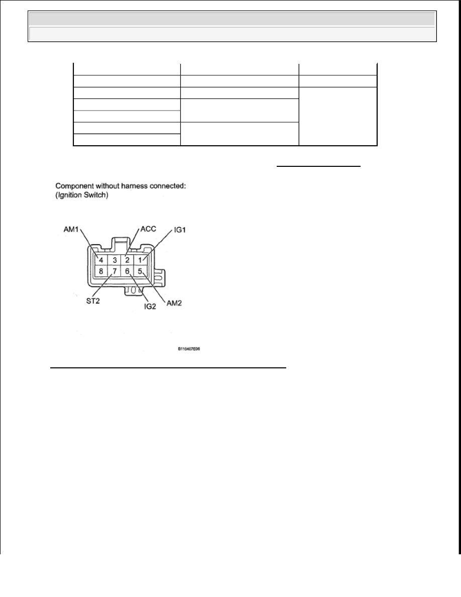
Fig. 267: Identifying J9 Ignition Switch Connector Terminals 

OK : REPAIR OR REPLACE HARNESS OR CONNECTOR  

VC OUTPUT CIRCUIT 

DESCRIPTION 

The ECM constantly generates 5 V power from the battery voltages supplied to the +B (BATT) terminal to 
operate the microprocessor. The ECM also provides this power to the sensors through the VC output circuit. 

Tester Connection

Switch Condition

Specified Condition

All Terminals

Ignition switch position LOCK 10 kohms or higher

2 (ACC) - 4 (AM1)

Ignition switch position ACC

Below 1 ohms

1 (IG1) - 2 (ACC) - 4 (AM1)

Ignition switch position ON

5 (AM2) - 6 (IG2)

1 (IG1) - 3 (ST1) - 4 (AM1)

Ignition switch position START

5 (AM2) - 6 (IG2) - 7 (ST2)


2008 Toyota Tundra 

2008 ENGINE PERFORMANCE Engine Control System (1GR-FE) - Tundra


Fig. 268: VC Output Circuit - Circuit Diagram 

When the VC circuit is short-circuited, the microprocessor in the ECM and sensors that are supplied with power 
through the VC circuit are inactivated because the power is not supplied from the VC circuit. Under this 
condition, the system does not start up and the MIL does not illuminate even if the system malfunctions. 

HINT: 

Under normal conditions, the MIL is illuminated for several seconds when the ignition switch is first turned 
ON. The MIL goes off when the engine is started. 

WIRING DIAGRAM 


2008 Toyota Tundra 

2008 ENGINE PERFORMANCE Engine Control System (1GR-FE) - Tundra


Fig. 269: VC Output Circuit - Wiring Diagram (1 Of 2) 


2008 Toyota Tundra 

2008 ENGINE PERFORMANCE Engine Control System (1GR-FE) - Tundra


Fig. 270: VC Output Circuit - Wiring Diagram (2 Of 2) 

INSPECTION PROCEDURE 

1. CHECK MIL 

a. Check that the Malfunction Indicator Lamp (MIL) lights up when turning the ignition switch ON. 

Result  

RESULT CHART 

A : SYSTEM OK  

B : Go to next step.  

Result

Proceed To

MIL illuminates

A

MIL does not illuminate

B


2008 Toyota Tundra 

2008 ENGINE PERFORMANCE Engine Control System (1GR-FE) - Tundra


Content   ..  1268  1269  1270  1271   ..