Toyota Tundra. Manual - part 1195


  Index      Toyota     Toyota Tundra (2007-2010 year) - Service and Repair Manual


Search            copyright infringement  


Content   ..  1193  1194  1195  1196   ..


Toyota Tundra. Manual - part 1195


DTC TROUBLE DETECTION CONDITION CHART 

Reference: Inspection using an oscilloscope. 

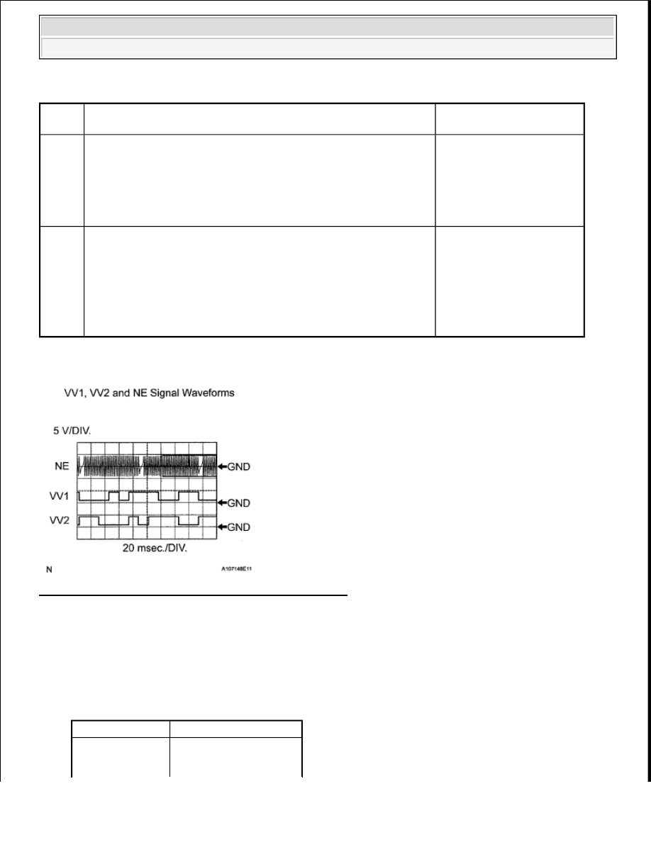
Fig. 119: Identifying VV1, VV2 & NE Signal Waveforms 

HINT: 

The correct waveform is as shown.  

VV1+ and VV2+ stand for the VVT sensor signal, and NE+ stands for the CKP sensor signal.  

Grounding failure of the shielded wire may cause noise in waveforms. 

WAVEFORM REFERENCES 

DTC 

No.

DTC Detection Condition

Trouble Area

P0335

When either condition below is met: 

No CKP sensor signal to ECM while cranking (1 trip 
detection logic)  

No CKP sensor signal to ECM at engine speed of 600 RPM 
or more (1 trip detection logic)  

Open or short in CKP 
sensor circuit  

CKP sensor  

CKP sensor plate  

ECM  

P0339

Under conditions (a), (b) and (c), no CKP sensor signal to ECM for 
0.05 seconds or more (1 trip detection logic): 

a. Engine speed 1000 RPM or more  

b. Starter signal OFF  

c. 3 seconds or more have elapsed since starter signal switched 

from ON to OFF  

Open or short in CKP 
sensor circuit  

CKP sensor  

CKP sensor plate  

ECM  

Item

Content

Terminal

VV1+ - VV1- 
VV2+ - VV2- 


2008 Toyota Tundra 

2008 ENGINE PERFORMANCE Engine Control System (1GR-FE) - Tundra


MONITOR DESCRIPTION 

If there is no signal from the CKP sensor despite the engine revolving, the ECM interprets this as a malfunction 
of the sensor. 

If the malfunction is not repaired successfully, a DTC is set 10 seconds after the engine is next started. 

MONITOR STRATEGY 

MONITOR STRATEGY 

TYPICAL ENABLING CONDITIONS 

All:  

TYPICAL ENABLING CONDITIONS 

Case 1:  

TYPICAL ENABLING CONDITIONS 

Case 2:  

TYPICAL ENABLING CONDITIONS 

NE+ - NE-

Equipment Setting 5 V/DIV., 20 msec./DIV.

Condition

Cranking or idling

Related DTCs

P0335: CKP sensor range check or rationality

Required Sensors/Components (Main)

CKP sensor

Required Sensors/Components (Related)

VVT sensor

Frequency of Operation

Continuous

Duration

3 times

MIL Operation

Immediate

Sequence of Operation

None

Monitor runs whenever following DTCs not present

None

Time after starter OFF to ON

0.3 seconds or more

Number of VVT sensor signal pulse

6 times

Battery voltage

7 V or more

Ignition switch

ON

Starter

OFF

Engine speed

600 RPM or more

Time after starter from ON to OFF

3 seconds or more


2008 Toyota Tundra 

2008 ENGINE PERFORMANCE Engine Control System (1GR-FE) - Tundra


TYPICAL MALFUNCTION THRESHOLDS 

Case 1:  

TYPICAL MALFUNCTION THRESHOLDS 

Case 2:  

TYPICAL MALFUNCTION THRESHOLDS 

COMPONENT OPERATING RANGE 

COMPONENT OPERATING RANGE 

WIRING DIAGRAM 

Fig. 120: Crankshaft Position Sensor Wiring Diagram 

INSPECTION PROCEDURE 

HINT: 

If no problem is found through this diagnostic troubleshooting procedure, troubleshoot the engine 
mechanical systems.  

Check the engine speed. The engine speed can be checked by using the Techstream. To check, follow the 
operation below: 

a. Connect the Techstream to the DLC3.  

b. Start the engine.  

c. Turn the Techstream ON.  

Number of CKP sensor signal pulse

132 or less, and 174 or more

Engine speed signal

No signal

CKP sensor

CKP sensor output voltage fluctuates while crankshaft revolving  

34 CKP sensor signals per crankshaft revolution  


2008 Toyota Tundra 

2008 ENGINE PERFORMANCE Engine Control System (1GR-FE) - Tundra


d. Enter the following menus: Powertrain/Engine and ECT/Data List/All Data/Engine Speed. The 

engine speed may be indicated as zero despite the engine revolving normally. This is caused by a 
lack of NE signals from the Crankshaft Position (CKP) sensor. Alternatively, the engine speed may 
be indicated as lower than the actual engine speed if the CKP sensor output voltage is insufficient.  

Read freeze frame data using the Techstream. Freeze frame data records the engine condition when 
malfunctions are detected. When troubleshooting, freeze frame data can help determine if the vehicle was 
moving or stationary, if the engine was warmed up or not, if the air-fuel ratio was lean or rich, and other 
data from the time the malfunction occurred.  

1. READ VALUE USING TECHSTREAM (ENGINE SPEED) 

a. Connect the Techstream to the DLC3.  

b. Turn the ignition switch ON.  

c. Turn the Techstream ON.  

d. Enter the following menus: Powertrain/Engine and ECT/Data List/All Data/Engine Speed.  

e. Start the engine.  

f. Read the values displayed on the Techstream while the engine is running. 

Standard:  

Correct values are displayed.  

HINT: 

To check the engine speed change, display the graph on the Techstream.  

If the engine does not start, check the engine speed while cranking.  

If the engine speed indicated on the Techstream remains at zero (0), there may be an open or 
short in the Crankshaft Position (CKP) sensor circuit.  

NG : Go to step 2  

OK : CHECK FOR INTERMITTENT PROBLEMS (See CHECK FOR INTERMITTENT 
PROBLEMS
 ) 

2. INSPECT CRANKSHAFT POSITION SENSOR (RESISTANCE) 

a. Disconnect the D4 Crankshaft Position (CKP) sensor connector.  

b. Measure the resistance according to the value(s) in the table below. 

Standard resistance  

TESTER CONNECTION SPECIFIED CONDITION 

Tester Connection Condition Specified Condition

1 - 2

Cold

985 to 1600 ohms

1 - 2

Hot

1265 to 1890 ohms


2008 Toyota Tundra 

2008 ENGINE PERFORMANCE Engine Control System (1GR-FE) - Tundra


Content   ..  1193  1194  1195  1196   ..