Toyota Tundra. Manual - part 1161


  Index      Toyota     Toyota Tundra (2007-2010 year) - Service and Repair Manual


Search            copyright infringement  


Content   ..  1159  1160  1161  1162   ..


Toyota Tundra. Manual - part 1161


b. Measure the resistance according to the value(s) in the table below. 

Standard resistance  

TESTER CONNECTION SPECIFIED CONDITION 

NG : CHECK FOR SHORT IN ALL HARNESSES AND CONNECTORS CONNECTED TO 
FUSE AND REPLACE FUSE
  

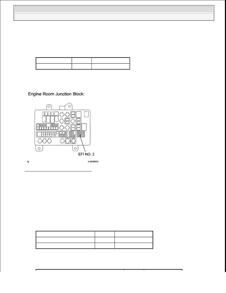
Fig. 50: Identifying EFI NO. 2 Fuse 

OK : Go to next step  

5. CHECK HARNESS AND CONNECTOR (HEATED OXYGEN SENSOR - EFI NO. 2 FUSE) 

a. Disconnect the D31 *1 or D32*2 HO2 sensor connector.  

b. Remove the EFI NO. 2 fuse from the engine room relay block.  

c. Measure the resistance according to the value(s) in the table below. 

Standard resistance (Check for open)  

TESTER CONNECTION SPECIFIED CONDITION 

Standard resistance (Check for short)  

TESTER CONNECTION SPECIFIED CONDITION 

Tester Connection Condition Specified Condition

EFI NO. 2 fuse

Always

Below 1 ohms

Tester Connection

Condition Specified Condition

D31-2 (+B) - EFI NO. 2 fuse (2) Always

Below 1 ohms

D32-2 (+B) - EFI NO. 2 fuse (2) Always

Below 1 ohms


2008 Toyota Tundra 

2008 ENGINE PERFORMANCE Engine Control System (1GR-FE) - Tundra


NG : REPAIR OR REPLACE HARNESS OR CONNECTOR  

Fig. 51: Identifying D31 *1 Or D32*2 HO2 Sensor Connector Terminals 

OK : Go to next step  

6. CHECK HARNESS AND CONNECTOR (INTEGRATION RELAY - EFI NO. 2 FUSE) 

a. Remove the EFI NO. 2 fuse from the engine room relay block.  

b. Remove the integration relay from the engine room junction block (See ON-VEHICLE 

INSPECTION ).  

c. Measure the resistance according to the value(s) in the table below. 

Tester Connection

Condition Specified Condition

D31-2 (+B) or EFI NO.2 fuse (2) - Body ground

Always

10 kohms or higher

D32-2 (+B) or EFI NO. 2 fuse (2) - Body ground Always

10 kohms or higher


2008 Toyota Tundra 

2008 ENGINE PERFORMANCE Engine Control System (1GR-FE) - Tundra


Standard resistance (Check for open)  

TESTER CONNECTION SPECIFIED CONDITION 

Standard resistance (Check for short)  

TESTER CONNECTION SPECIFIED CONDITION 

NG : REPLACE ENGINE ROOM RELAY BLOCK, JUNCTION BLOCK  

Fig. 52: Identifying Integration Relay - EFI No. 2 Fuse 

Tester Connection

Condition Specified Condition

EFI NO. 2 fuse(1) - 1B-4 Always

Below 1 ohms

Tester Connection

Condition Specified Condition

EFI NO. 2 fuse (1) or 1B-4 - Body ground Always

10 kohms or higher


2008 Toyota Tundra 

2008 ENGINE PERFORMANCE Engine Control System (1GR-FE) - Tundra


OK : CHECK ECM POWER SOURCE CIRCUIT (See ECM POWER SOURCE CIRCUIT ) 

DTC P0101 MASS AIR FLOW CIRCUIT RANGE/PERFORMANCE PROBLEM 

DESCRIPTION 

Refer to DTC P0100 . 

DTC TROUBLE DETECTION CONDITION CHART 

MONITOR DESCRIPTION 

The MAF meter is a sensor that measures the amount of air flowing through the throttle valve. The ECM uses 
this information to determine the fuel injection time and to provide an appropriate air-fuel ratio. Inside the MAF 
meter, there is a heated platinum wire which is exposed to the flow of intake air. By applying a specific 
electrical current to the wire, the ECM heats it to a specific temperature. The flow of incoming air cools both 
the wire and an internal thermistor, affecting their resistance. To maintain a constant current value, the ECM 
varies the voltage applied to the wire and internal thermistor of the MAF meter. The voltage level is 
proportional to the airflow through the sensor, and the ECM uses it to calculate the intake air volume. 

The ECM monitors the average engine load value ratio to check the MAF meter for malfunctions. The average 
engine load value ratio is obtained by comparing the average engine load calculated from the MAF meter output 
to the average engine load estimated from the driving conditions, such as the engine speed and the throttle 
opening angle. If the average engine load value ratio is below the threshold value, the ECM determines that the 
intake air volume is low, and if the average engine load value ratio is above the threshold value, the ECM 
determines that the intake air volume is high. 

If this is detected in 2 consecutive driving cycles, the MIL is illuminated and a DTC is set. 

MONITOR STRATEGY 

MONITOR STRATEGY 

DTC 

No.

DTC Detection Condition

Trouble Area

P0101

Conditions (a), (b), (c), (d) and (e) continue for more than 10 seconds (2 
trip detection logic) 

a. Engine running  

b. Engine coolant temperature 70°C (158°F) or higher  

c. Throttle Position (TP) sensor voltage 0.2 to 2 V  

d. Average engine load value ratio less than 0.85, or more than 1.17 

(varies with estimated engine load) Average engine load value ratio 
= Average engine load based on MAF meter output/Average engine 
load estimated from driving conditions  

e. Average air-fuel ratio less than -15%, or more than 15%  

Mass Air Flow 
(MAF) meter  

Air induction 
system  

PCV hose 
connections  

Related DTCs

P0101: Mass air flow meter rationality


2008 Toyota Tundra 

2008 ENGINE PERFORMANCE Engine Control System (1GR-FE) - Tundra


Content   ..  1159  1160  1161  1162   ..