Suzuki Grand Vitara JB416 / JB420 / JB419. Manual - part 504
9F-3 Security and Locks:
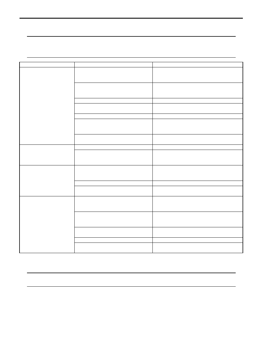
Keyless Entry System Symptom Diagnosis (If Equipped)
S6JB0A9604003
NOTE
• Confirm that power door lock system is in good condition before referring to the following possible
causes.
• Check each part in the order from the top of the following list.
Keyless Entry System Operation Inspection
S6JB0A9604004
NOTE
When performing the this inspection, make sure to have any of the door once opened / closed after the
ignition key has been removed from the ignition key cylinder.
Condition
Possible cause
Correction / Reference Item
All door can not be locked
/ unlocked by only
keyless entry transmitter
Transmitter battery dead
Replace battery referring to “Replacement of
Transmitter Battery (Other than Keyless Start
Model)”.
Door switch faulty
Check door switch referring to “Door Switch
(Front / Rear / Rear End Door) Inspection in
Section 9C”.
Transmitter faulty
Replace transmitter.
Key reminder switch in ignition switch
faulty
Check ignition switch referring to “Ignition
Switch Inspection in Section 9C”.
Wiring or grounding faulty
Repair circuit.
Keyless entry receiver faulty
Check keyless entry receiver referring to
“Keyless Entry Receiver and Its Circuit
Inspection (If Equipped)”.
BCM faulty
Replace after making sure that none of above
parts is faulty.
Interior light does not
light when doors are
unlocked by keyless entry
transmitter
Wiring or grounding faulty
Repair circuit.
BCM faulty
Replace after making sure that none of above
parts is faulty.
Hazard warning lights do
not light when doors are
locked/unlocked by
keyless entry transmitter
Turn signal and hazard warning relay
faulty
Check turn signal and hazard warning relay
referring to “Turn Signal and Hazard Warning
Relay Inspection in Section 9B”.
Wiring or grounding faulty
Repair circuit.
BCM faulty
Replace after making sure that none of above
parts is faulty.
Transmitter code can not
be programmed to BCM
Door switch faulty
Check door switch referring to “Door Switch
(Front / Rear / Rear End Door) Inspection in
Section 9C”.
Keyless entry receiver faulty
Check keyless entry receiver referring to
“Keyless Entry Receiver and Its Circuit
Inspection (If Equipped)”.
Key reminder switch in ignition switch
faulty
Check ignition switch referring to “Ignition
Switch Inspection in Section 9C”.
Wiring or grounding faulty
Repair circuit.
BCM faulty
Replace after making sure that none of above
parts is faulty.