Suzuki Grand Vitara JB416 / JB420 / JB419. Manual - part 361
6B-2 Steering Wheel and Column:
16
10
(b)
17
(b)
9
8
4
6
7
15
(c)
14
(c)
12
(b)
2
(a)
5
1
11
(b)
13
3
18
I6JB0A620001-01
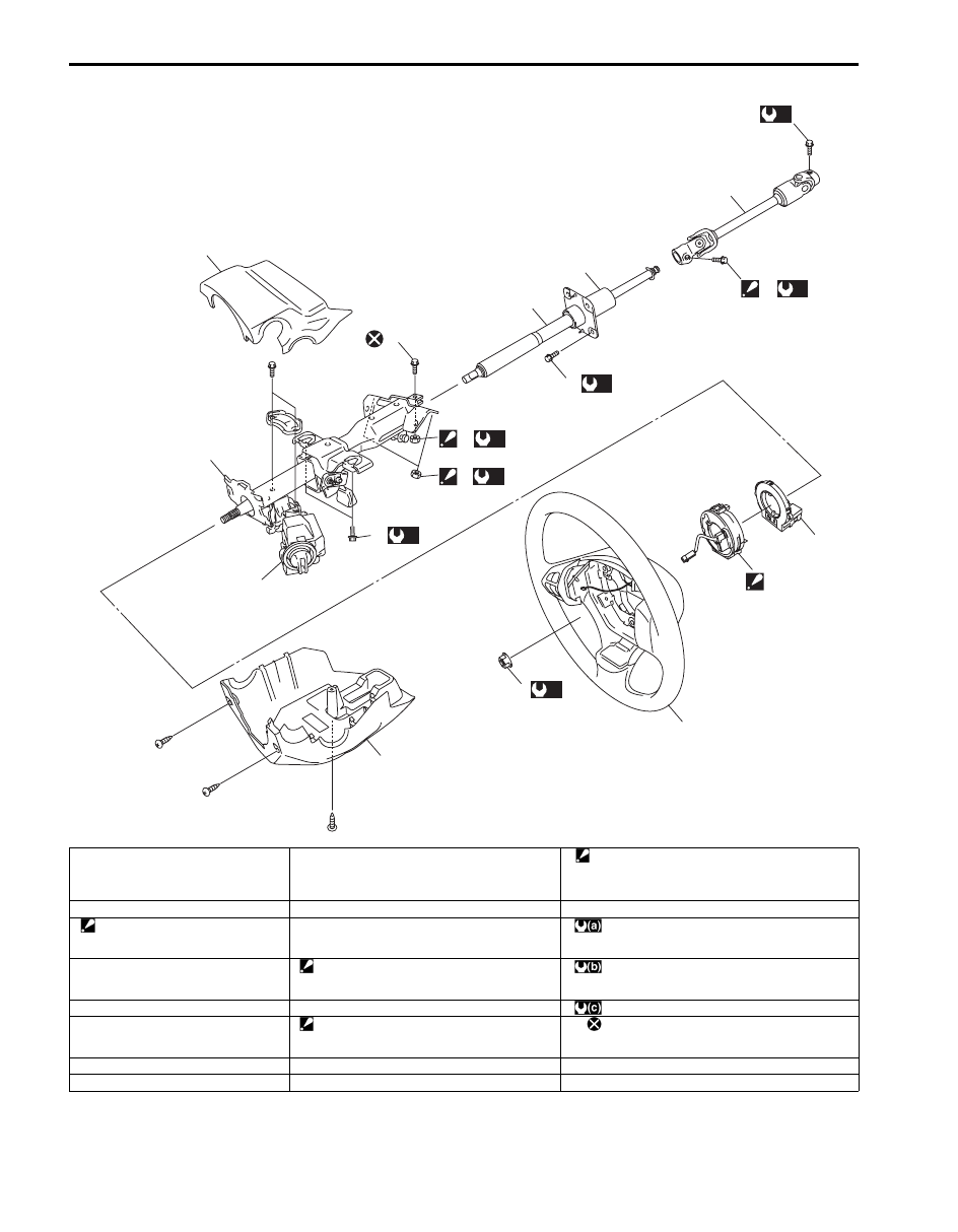
1. Steering wheel
9. Steering column lower seal
17. Steering lower shaft assembly upper joint bolt
: After tightening all mounting bolts and nuts and
all joint bolts and nuts, tighten lower shaft lower
joint bolt.
2. Steering shaft nut
10. Steering lower shaft assembly
18. Steering angle sensor (ESP
® model)
3. Contact coil cable assembly
: Fit lower fitting part first and then
fit upper fitting part.
11. Steering column assembly mounting bolt
: 33 N
⋅m (3.3 kgf-m, 24.0 lb-ft)
4. Steering column upper cover
12. Steering column assembly mounting nut
: After tightening column mounting nut, tighten
column mounting bolt.
: 25 N
⋅m (2.5 kgf-m, 18.0 lb-ft)
5. Steering column lower cover
13. Steering upper shaft assembly upper joint bolt
: 23 N
⋅m (2.3 kgf-m, 17.0 lb-ft)
6. Steering column assembly
14. Steering upper shaft assembly upper joint nut
: After tightening upper shaft mounting bolts,
tighten upper shaft joint nut.
: Do not reuse.
7. Steering lock assembly
15. Steering upper shaft mounting bolt
8. Steering upper shaft assembly
16. Steering lower shaft assembly lower joint bolt