Suzuki Grand Vitara JB416 / JB420 / JB419. Manual - part 222
2C-11 Rear Suspension:
2) Tighten parking cable hanger bolt (1) to specified
torque.
Tightening torque
Parking cable hanger bolt (a): 10 N·m (1.0 kgf-
m, 7.5 lb-ft)
3) Lower jack and remove floor jack from lower arm.
4) Install rear wheels and lower hoist.
5) Tighten wheel nuts to specified torque.
Tightening torque
Wheel nut: 100 N·m (10.0 kgf-m, 72.5 lb-ft)
6) Tighten control rod mount nut and control rod outer
bolt to specified torque with vehicle weight on
suspension.
CAUTION
!
• It is the most desirable to have vehicle off
hoist and in non-loaded condition when
tightening them.
• Tighten control rod washer with match
marks aligned.
Tightening torque
Control rod mount nut: 135 N·m (13.5 kgf-m,
98.0 lb-ft)
Control rod outer bolt: 135 N·m (13.5 kgf-m, 98.0
lb-ft)
7) Check rear toe and camber adjust it as necessary.
For check and adjustment procedures, refer to “Rear
Wheel Alignment Inspection and Adjustment”.
Control Rod / Bushing Disassembly and
Assembly
S6JB0A2306009
Disassembly
1) Push out control rod bushing by using hydraulic
press (1) and special tool.
Special tool
(A): 09913–84510
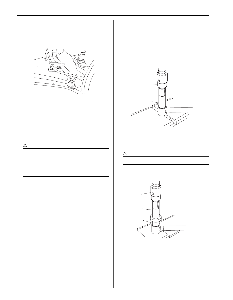
Assembly
1) Press-fit control rod bushing (1) by using press (2)
and special tool.
CAUTION
!
Be sure to use new bushing.
Special tool
(A): 09913–85210
1,(a)
I5JB0A230022-01
(A)
1
I5JB0A230023-02
1
2
(A)
I5JB0A230082-01