Suzuki Grand Vitara JB416 / JB420 / JB419. Manual - part 184


  Index      Suzuki     Suzuki Grand Vitara JB416 / JB420 / JB419 - service repair manual 2007 year


Search            


Content   ..  182  183  184  185   ..


Suzuki Grand Vitara JB416 / JB420 / JB419. Manual - part 184


1G-9 Fuel System: For Petrol Engine Model

The other than fuel tank system

For Quick Joint (other than Fuel Vapor Line)
Disconnecting

1) Remove mud, dust and/or foreign material between 

pipe (1) and quick joint (2) by blowing compressed 
air.

2) Unlock joint lock by inserting special tool between 

pipe and quick joint.

Special tool
(A):  09919–47020

3) Disconnect quick joint from pipe.

Reconnecting
Insert quick joint to fuel pipe until they lock securely (a 
click is heard), and confirm that quick joint is not 
disconnected by hand.

For Quick Joint (Fuel Vapor Line)
Disconnecting

1) Remove mud, dust and/or foreign material between 

pipe (1) and quick joint (fuel vapor line) (2) by 
blowing compressed air.

2) Release lock plate (3) completely in arrow direction, 

and then remove quick joint (fuel vapor line) (2) from 
fuel pipe (4).

Reconnecting

1) Connect quick joint (fuel vapor line) (1) to fuel pipe 

(2), and then push lock plate (3) completely in arrow 
direction.

2) Confirm that quick joint is not disconnected by hand.

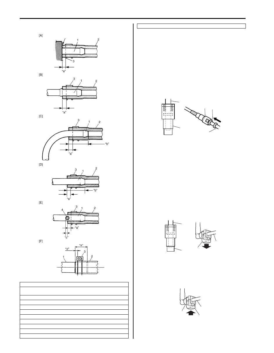
[A]: With short pipe, fit hose as far as it reaches pipe joint as shown.
[B]: With the following type pipe, fit hose as far as its peripheral projection 

as shown.

[C]: With bent pipe, fit hose as its bent part as shown or till depth “b”.
[D]: With straight pipe, fit hose till depth “b”.

[E]: With red marked pipe, fit hose end reaches red mark on pipe.

[F]: For fuel tank filler hose, insert it to spool or welding-bead.

“a”: Clamp securely at a position 3 – 7 mm (0.12 – 0.27 in.) from hose end.
“b”: 20 – 30 mm (0.79 – 1.18 in.)

“c”: 0 – 5 mm (0 – 0.19 in.)

“d”: 5 – 12 mm (0.2 – 0.47 in.)
“e”: 40 mm (1.57 in.)

I3RM0A170001-01

4. Red mark

1

2

1

2

(A)

I4RS0A170019-01

3

4

1

2

I5JB0A171004-01

2

3

1

I5JB0A171005-01

Fuel System: For Petrol Engine Model 1G-10

Fuel Pressure Relief Procedure

S6JB0A1716003

CAUTION

!


This work must not be done when engine is 
hot. If done so, it may cause adverse effect to 
catalyst.


NOTE
If ECM detects DTC(s) after servicing, clear 
DTC(s) referring to “DTC Clearance: For 
Petrol Engine Model in Section 1A”.


1) Make sure that engine is cold.
2) Shift transaxle gear shift lever in “Neutral” (shift 

select lever in “P” range for A/T model), set parking 
brake and block drive wheels.

3) Remove fuse box No.2 cover.
4) Disconnect fuel pump relay (1) from fuse box No.2 

(2).

5) Remove fuel filter cap in order to release fuel vapor 

pressure in fuel tank, and then reinstall it.

6) Start engine and run it until engine stops for lack of 

fuel. Repeat cranking engine 2 – 3 times for about 3 
seconds each time in order to dissipate fuel pressure 
in lines. Fuel connections are now safe for servicing.

7) After servicing, connect fuel pump relay (1) to fuse 

box No.2 and install fuse box No.2 cover.

Fuel Leakage Check Procedure

S6JB0A1716004

After performing any service on fuel system, check to 
make sure that there are no fuel leakages as follows.

1) Turn ON ignition switch for 3 seconds (to operate 

fuel pump) and then turn it OFF.
Repeat this (ON and OFF) 3 or 4 times and apply 
fuel pressure to fuel line until fuel pressure is felt by 
hand placed on fuel feed hose.

2) In this state, check to see that there are no fuel 

leakages from any part of fuel system.

Fuel Lines On-Vehicle Inspection

S6JB0A1716005

CAUTION

!


Due to the fact that fuel feed line (1) is under 
high pressure, use special care when 
servicing it.


Visually inspect fuel lines for evidence of fuel leakage, 
hose crack and deterioration or damage.
Make sure all clamps are secure.
Replace parts as needed.

Fuel Pipe Removal and Installation

S6JB0A1716006

WARNING

!


Before starting the following procedure, be 
sure to observe “Precautions on Fuel System 
Service: For Petrol Engine Model” in or
der to 
reduce the risk or fire and personal injury.


Removal

1) Relieve fuel pressure in fuel feed line according to 

“Fuel Pressure Relief Procedure: For Petrol Engine 
Model”.

2) Disconnect negative cable at battery.
3) Disconnect fuel pipe joint and fuel hose (3) from fuel 

pipe (2) at the front and rear of each fuel pipe 
referring to “Fuel Hose Disconnecting and 
Reconnecting: For Petrol Engine Model”.

4) Mark the location of clamps (1) on fuel pipes (2), so 

that the clamps can be reinstalled to where they 
were.

5) Remove pipes (2) with clamp (1) from vehicle.
6) Remove clamp (1) from pipes (2).

1

2

I5JB0A171006-01

I6JB0A171004-01

1G-11 Fuel System: For Petrol Engine Model

Installation

1) Install clamps to marked

®® location on pipes. If 

clamp is deformed, its claw is bent or broken, 
replace it with new one.

2) Install pipes with pipe clamps to vehicle.

NOTE
For M16 engine model, be sure to tighten fuel 
pipe bolt as specified tightening order 
described in “Fuel System Components: For 
Petrol Engine Model”.


3) Connect fuel hoses and pipes to each pipe referring 

to “Fuel Hose Disconnecting and Reconnecting: For 
Petrol Engine Model”.

4) Connect negative cable at battery.
5) With engine OFF, turn ignition switch to ON position 

and check for fuel leaks.

Fuel Injector On-Vehicle Inspection

S6JB0A1716007

1) Using sound scope (1) or such, check operating 

sound of injector (2) when engine is running or 
cranking.
Cycle of operating sound should vary according to 
engine speed.
If no sound or an unusual sound is heard, check 
injector circuit (wire or coupler) or injector.

2) Disconnect connector (1) from injector, connect 

ohmmeter between terminals of injector and check 
resistance.

Reference resistance of fuel injector
12 

 at 20 °C, 68 °F

3) Connect connector to injector securely.

Fuel Injector Removal and Installation

S6JB0A1716008

WARNING

!


Before starting the following procedure, be 
sure to observe “Precautions on Fuel System 
Service: For Petrol Engine Model” in or
der to 
reduce the risk or fire and personal injury.


Removal

1) Relieve fuel pressure according to “Fuel Pressure 

Relief Procedure: For Petrol Engine Model”.

2) Disconnect negative cable at battery.
3) Disconnect fuel injector couplers.
4) Disconnect fuel feed hose from fuel delivery pipe (1).
5) Disconnect fuel return hose from pressure regulator.
6) Disconnect vacuum hose from pressure regulator.
7) Remove fuel delivery pipe bolts (2).
8) Remove fuel injector(s) (3).

1

2

I5JB0A171007-01

I2RH0B170008-01

[A]: For M16 engine model

[B]: For J20 engine model

I5JB0A170007-02

Fuel System: For Petrol Engine Model 1G-12

Installation
Reverse removal procedure for installation noting the 
following.
• Replace injector O-ring (1) with new one using care 

not to damage it.

• Check if cushion (2) is scored or damaged. If it is, 

replace with new one.

• Apply O-ring oil to O-rings (1), and then install 

injectors (3) into delivery pipe (4) and cylinder head.
Make sure that injectors rotate smoothly (6). If not, 
probable cause is incorrect installation of O-ring. 
Replace O-ring with new one.

“A”:  Oil 99000–25320 (SUZUKI DI O RING 
OIL(500CC))

• Tighten delivery pipe bolts (5) to specified torque and 

make sure that injectors rotate smoothly.

Tightening torque
Fuel delivery pipe bolt (a):  25 N·m (2.5 kgf-m, 18.0 
lb-ft)

• After installation, with engine OFF and ignition switch 

ON, check for fuel leaks around fuel line connection.

Fuel Injector Inspection

S6JB0A1716009

WARNING

!


Before starting the following procedure, be 
sure to observe “Precautions on Fuel System 
Service: For Petrol Engine Model” in or
der to 
reduce the risk or fire and personal injury.


1) Install injector to special tool (injector checking tool).
2) Install pressure regulator to special tool (injector 

checking tool).

Special tool
(A):  09912–58421
(B):  09912–58442

3) Connect special tools (hose and attachment) to fuel 

feed pipe (1) of vehicle.

I5JB0A170008-02

[A]: For M16 engine model

[B]: For J20 engine model

I5JB0A171008-02


Content   ..  182  183  184  185   ..