Suzuki Grand Vitara JB416 / JB420 / JB419. Manual - part 130
1D-46 Engine Mechanical: For M16A Engine with VVT
Piston clearance
Standard: 0.032 – 0.061 mm (0.0013 – 0.0024 in.)
Standard (piston with coating (new one)): 0.016 –
0.045 mm (0.0006 – 0.0018 in.)
Limit: 0.161 mm (0.0065 in.)
Ring groove clearance
Before checking, piston grooves must be clean, dry and
free of carbon deposits.
Fit new piston ring (1) into piston groove, and measure
clearance between ring and ring land by using thickness
gauge (2). If clearance is out of specification, replace
piston.
Ring groove clearance
Piston Ring
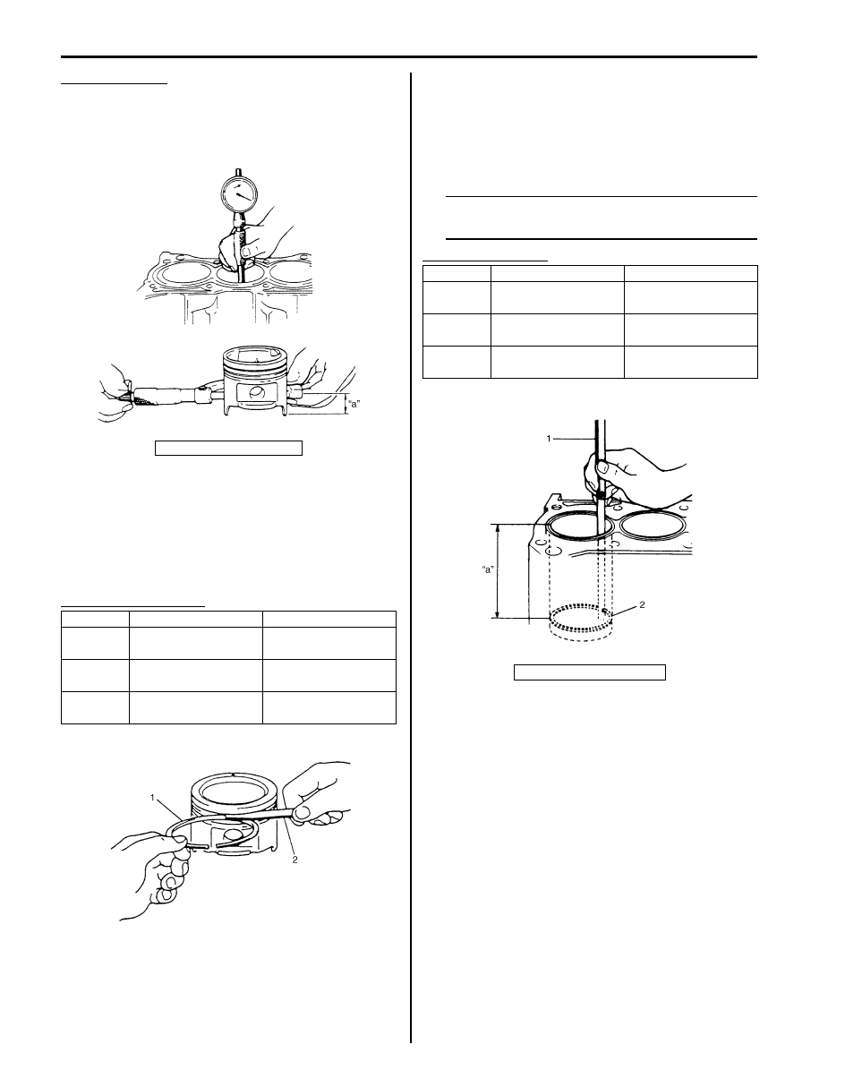
Piston ring end gap
To measure end gap, insert piston ring (2) into cylinder
bore and then measure the gap by using thickness
gauge (1).
If measured gap exceeds limit, replace ring.
NOTE
Decarbonize and clean top of cylinder bore
before inserting piston ring.
Piston ring end gap
“a”: 19.5 mm (0.77 in.)
Standard
Limit
Top ring
0.03 – 0.07 mm
(0.0012 – 0.0028 in.)
0.12 mm (0.0047 in.)
2nd ring
0.02 – 0.06 mm
(0.0008 – 0.0024 in.)
0.10 mm (0.0039 in.)
Oil ring
0.03 – 0.17 mm
(0.0012 – 0.0067 in.)
—
I4RS0A140022-01
I2RH01140159-01
Item
Standard
Limit
Top ring
0.20 – 0.35 mm
(0.0079 – 0.0138 in.)
0.7 mm (0.0276 in.)
2nd ring
0.35 – 0.50 mm
(0.0138 – 0.0197 in.)
1.0 mm (0.0394 in.)
Oil ring
0.20 – 0.70 mm
(0.0079 – 0.0276 in.)
1.2 mm (0.0472 in.)
“a”: 120 mm (4.72 in.)
I2RH01140161-01