Suzuki Grand Vitara JB416 / JB420 / JB419. Manual - part 86
1A-291 Engine General Information and Diagnosis: For Diesel Engine Model
DTC P0033: Boost Pressure Control Solenoid Valve Control Circuit
S6JB0A1124090
CAUTION
!
This fault can result in a rapid and significant fouling of the diesel particulate filter.
NOTE
• Conditions for applying the fault finding procedure to stored faults:
The fault is declared present after:
– Engine start.
– A road test.
– Output test “Boost pressure valve” on SUZUKI scan tool.
• If the fault is present:
– Turbocharging is no longer authorized.
– The EGR function is inhibited.
– The vehicle performance is reduced.
– The Injection warning light (gravity 1 warning light) is lit.
– If CC0 is present, the Malfunction indicator light (MIL) will come on after three consecutive driving
cycles (starting +5 seconds + turn OFF ignition switch and wait 40 seconds.).
• Use service wire for all operations on the ECM connectors.
Wiring Diagram
For wiring circuit and connector number, refer to “A-5 Engine and A/C Control System Circuit Diagram (DSL) in
Section 9A”.
Detecting Condition
Troubleshooting for CC1: Short circuit to +12 V
Troubleshooting for CC0: Short circuit to vehicle body ground and CO: Open circuit
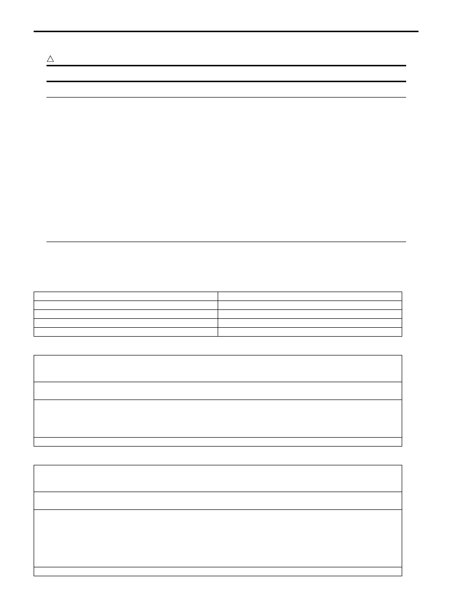
Displaying on SUZUKI scan tool
Detecting condition
CC1
Short circuit to +12 V
CC0
Short circuit to vehicle body ground
CO
Open circuit
D1
Internal electronic fault
Check the boost pressure control solenoid valve connections.
Check the ECM connections.
Repair if necessary.
Measure the resistance of the boost pressure control solenoid valve between its “C90-1” and “C90-2” terminals:
If the resistance displayed is not 14.7 – 16.1
Ω at 20 °C, 68 °F, replace the boost pressure control solenoid valve.
Check the continuity and insulation from the +12 V feed of the following connection:
• Between “C90-1” wire of boost pressure control solenoid valve connector and “C85-23” terminal of ECM
connector
Repair if necessary.
If the fault is still present, replace the boost pressure control solenoid valve.
Check the boost pressure control solenoid valve connections.
Check the ECM connections.
Repair if necessary.
Measure the resistance of the boost pressure control solenoid valve between its “C90-1” and “C90-2” terminals:
If the resistance displayed is not 14.7 – 16.1
Ω at 20 °C, 68 °F, replace the boost pressure control solenoid valve.
Check the continuity and insulation from vehicle body ground of the following connections:
• Between “C90-1” wire of boost pressure control solenoid valve connector and “C85-23” terminal of ECM
connector
• Between “C90-2” wire of boost pressure control solenoid valve connector and “E33-6” wire of main relay
mounting connector
Repair if necessary.
If the fault is still present, replace the boost pressure control solenoid valve.