Suzuki Grand Vitara JB416 / JB420 / JB419. Manual - part 21
1A-31 Engine General Information and Diagnosis: For Petrol Engine Model
DTC Check
S6JB0A1114003
NOTE
The MIL is turned on when the ECM and/or
TCM detect malfunction(s). Each ECM and
TCM stores diagnostic information as the
diagnostic trouble code (DTC) in its memory
and outputs the DTC to the scan tool.
Therefore, check both of the ECM and TCM
for any DTC with the scan tool because the
DTC stored in ECM and TCM is not read and
displayed at a time. However, each of the
ECM and TCM needs not to be checked with
the generic scan tool because the DTC stored
in ECM and TCM is read and displayed at a
time.
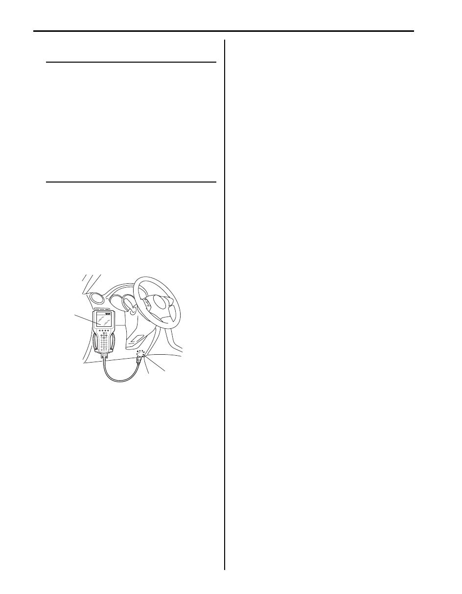
Using Scan Tool
1) Prepare SUZUKI scan tool or OBD generic scan tool
(Euro OBD model).
2) With ignition switch turned OFF, connect it to data
link connector (DLC) (1) located on underside of
instrument panel at driver’s seat side.
Special tool
(A): SUZUKI scan tool
3) Turn ignition switch ON and confirm that MIL lights.
4) Read DTC, pending DTC and freeze frame data
according to instructions displayed on scan tool and
print them or write them down. Refer to scan tool
operator’s manual for further details.
If communication between scan tool and ECM is not
possible, check if scan tool is communicable by
connecting it to ECM in another vehicle. If
communication is possible in this case, scan tool is
in good condition. Then check data link connector
and serial data line (circuit) in the vehicle with which
communication was not possible. If connector and
circuit are OK, check that power supply and ground
circuits of ECM and DLC are in good condition
referring to “ECM Power and Ground Circuit Check:
For Petrol Engine Model”.
5) After completing the check, turn ignition switch OFF
and disconnect scan tool from data link connector.
(A)
1
I5JB0A110019-01