Suzuki Grand Vitara JB416 / JB420 / JB419. Manual - part 16


  Index      Suzuki     Suzuki Grand Vitara JB416 / JB420 / JB419 - service repair manual 2007 year


Search            


Content   ..  14  15  16  17   ..


Suzuki Grand Vitara JB416 / JB420 / JB419. Manual - part 16


1A-11 Engine General Information and Diagnosis: For Petrol Engine Model

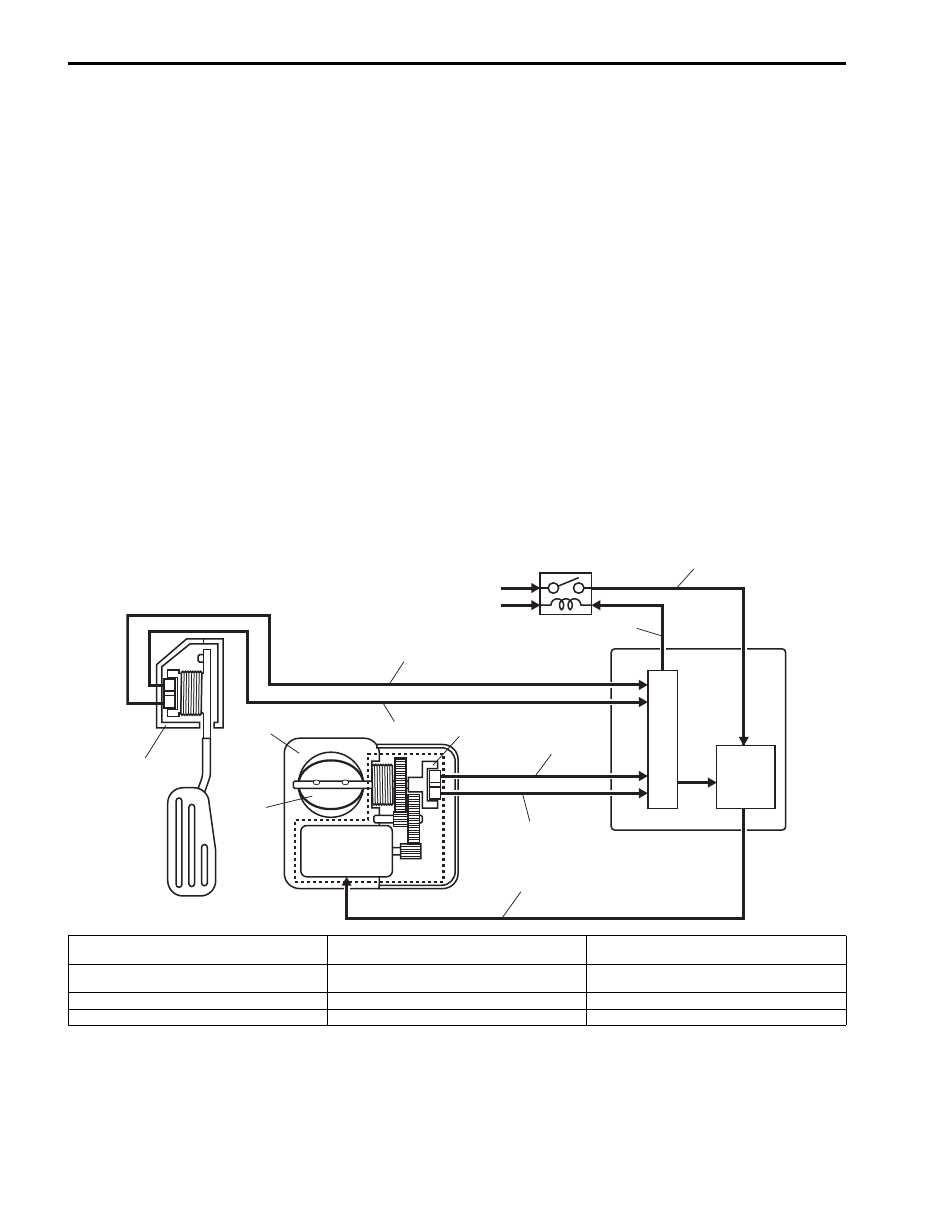
Electric Throttle Body System Description

S6JB0A1111007

The Electric Throttle Body System consists of electric throttle body assembly, accelerator pedal position (APP) sensor 
assembly, ECM and throttle actuator control relay.
Among them, assembly components are as follows.
• Electric throttle body assembly: throttle valve, throttle actuator, 2 throttle position sensors
• Accelerator pedal position (APP) sensor assembly: Accelerator pedal, 2 accelerator position sensors

Operation Description
ECM (5) detects opening (depressed extent of pedal) of the accelerator pedal based on signal voltage of the 
accelerator pedal position (APP) sensor (1) and using that data and engine operation condition, it calculates the 
optimum throttle valve opening. On the other hand, it detects the throttle valve opening based on the signal voltage of 
the throttle position sensor (3) included in the throttle body (2) and compares it with the above calculated optimum 
throttle valve opening. When there is a difference between them, ECM controls the duty ratio (100% – 0%) of throttle 
actuator control according to this difference to drive the throttle actuator (motor) (4) included in the throttle body. When 
there is no difference, ECM controls the duty ratio of throttle actuator control to about 15% to maintain the throttle 
valve opening. In this way, the throttle valve (17) is opened and closed to achieve the optimum throttle valve opening.
In this system, as the throttle position sensor and accelerator pedal position (APP) sensor have 2 sensors (main and 
sub) each, highly accurate and highly reliable control and abnormality detection are assured. Also, when ECM detects 
an abnormality in the system, it turns off the throttle actuator control relay (8) to stop controlling the throttle actuator. 
When the throttle actuator control relay is turned off, the throttle valve is fixed at the opening of about 7

° from its 

completely closed position (default opening) by the force of the return spring and open spring included in the throttle 
body.
This throttle body is not equipped with IAC valve for idle speed control. Idle speed control is done by the throttle 
actuator which opens/closes the throttle valve.

4

1

2

17

3

5

6

7

8

9

10

11

12

13

14

15

16

18

I4RS0B110007-02

6. CPU

11.

Accelerator pedal position (APP) sensor 
(main) signal

15. Drive signal of throttle actuator

7. Drive circuit of throttle actuator

12.

Accelerator pedal position (APP) sensor (sub) 
signal

16. Power supply of throttle actuator

9. From “THR MOT” fuse

13.

Throttle position sensor (main) signal

18. Control signal of throttle actuator control relay

10. From main relay

14.

Throttle position sensor (sub) signal

Engine General Information and Diagnosis: For Petrol Engine Model 1A-12

Description of Electric Throttle Body System Calibration

S6JB0A1111008

ECM calculates controlled opening of the throttle valve on the basis of the completely closed throttle valve position of 
the electric throttle body system. The completely closed position data is saved in memory of ECM. However, the 
completely closed position of the throttle valve of the electric throttle body system (signal voltage from throttle position 
sensor when throttle is completely closed) differs one from the other depending on individual differences of the throttle 
valve and throttle position sensor. As such individual differences must be taken into account for controlling the throttle 
valve, it is necessary to register the completely closed throttle valve position data in ECM. When such data is 
registered in ECM, it is saved in RAM (memory) of ECM and used as the base data for controlling the throttle valve. 
This data is cleared, when any of the works described in “Precautions of Electric Throttle Body System Calibration: For 
Petrol Engine Model” is 
performed.
Also, after replacement of the throttle body and/or accelerator pedal position (APP) sensor assembly, the completely 
closed position data in memory of ECM must be cleared once and a new one must be registered, or ECM cannot 
judge the complete closure position properly.
For the procedure to register such data, refer to “Electric Throttle Body System Calibration: For Petrol Engine Model in 
Section 1C”. (Af
ter the completely closed position data is cleared, ECM, for the first time only, opens and closes the 
throttle valve for about 5 seconds after the ignition switch is turned ON position, for registration of the completely 
closed throttle valve position. If the engine is started during this registration process, such symptom as “longer 
cranking time” or “slow rise of revolution speed immediately after start-up” may occur. However, turning OFF the 
ignition switch once and restarting will set correct registration.)

Generator Control System Description

S6JB0A1111009

Generator Control System consists of a generator (1), electric load current sensor (7) (for J20 engine) located in the 
fuse box No.1 (4) and ECM (5).
ECM controls generated electricity (adjusting voltage of IC regulator (2)) so that it is suitable for the engine and electric 
load conditions. When the electric load increases quickly, generation load of the generator increases quickly and 
causes idling to change. To prevent this, ECM makes generated electricity volume vary gradually to stabilize idling. 
Also, it reduces the engine load caused by temporary increase in electricity generation to cope with the engine 
condition (such as when accelerating).

Operation
ECM controls the generated voltage of the generator using “C” terminal (generator control terminal) duty, based on 
following information.
• Engine condition (ECT, vehicle speed, engine speed, TP, etc.) (9)
• Battery voltage (ECM backup power voltage) (10)
• Electric load condition (blower motor, rear defogger, head lights, radiator fan, A/C, etc.) (11)
• “FR” terminal output (field coil (3) control duty) which indicates the operation rate (electricity generation condition) of 

the generator.

Then the generator uses “C” terminal duty to regulate the adjusting voltage of the IC regulator with the field coil control 
duty so as to control its generated voltage (“B” terminal output voltage).
(For more information of the generated voltage, refer to Charging System in Section 1J.)
Furthermore, with the J20 engine, the generation condition of the generator is controlled to the optimum level by the 
electric load current sensor (7) which detects the electrical load condition (current consumption) linearly even when a 
sudden electrical load variation occurs and thus the engine load is reduced.

1A-13 Engine General Information and Diagnosis: For Petrol Engine Model

A/F Sensor Description

S6JB0A1111010

A/F sensor (1), in place of the conventional heated Oxygen sensor-1, is installed in the center of the exhaust manifold 
joining section and it consists of a zirconia element (2) which causes the output current to vary according to difference 
in the oxygen concentration, a heater (3) which activates the element and an adjusting resistor (4) which adjusts 
individual difference of the sensor (J20A engine).
A/F sensor detects oxygen concentration in exhaust gas (9) (A/F ratio of the air-fuel mixture) linearly, ranging from 
LEAN to RICH.

Operation
ECM (5) controls the sensor heater (3) and keeps the sensor element temperature at the specified level (about 750 

°C) constantly so that the A/F sensor is activated in the specified way for accurate A/F detection. When the sensor 
element reaches the specified temperature (it is activated), its impedance drops to the specified value (approx. 30 

Ω) 

by its characteristic.
When a certain voltage (about 0.4 V) is applied between sensor elements in this state, circuit current corresponding to 
the sensor element impedance flows in the sensor circuit. ECM detects this circuit current and judges whether the 
sensor is in the active state or not. At this time, sensor current is output linearly in the range of +0.01 mA to +some mA 
on the lean side and –0.01 mA to – some mA on the rich side. The variation in these ranges depends on the difference 
from the stoichiometry A/F ratio, that is, the amount of oxygen between the atmosphere side (6) and exhaust manifold 
(7).
According to this sensor output, ECM executes A/F feedback (fuel trim) to achieve the target A/F ratio.

The A/F sensor connector (8) is provided with an adjusting resistor (4) ECM detects the adjusting resistance value and 
corrects the sensor output current value (J20A engine).

IG

L

C

FR

E

2

B

1

3

5

CMO
CMG

CMV

FCD

GCD 

5V

11

10

9

8

7

4

6

I5JB0A110009-01

6. Ignition switch

8. Battery

Engine General Information and Diagnosis: For Petrol Engine Model 1A-14

Electronic Control System Description

S6JB0A1111011

The electronic control system consists of 1) various sensors which detect the state of engine and driving conditions, 2) 
ECM which controls various devices according to the signals from the sensors and 3) various controlled devices.
Functionally, it is divided into the following sub systems:
• Fuel injection control system
• Ignition control system
• Intake manifold tuning valve control system (J20A engine)
• Electric Throttle Body Control System
• Fuel pump control system
• Radiator cooling fan control system
• Evaporative emission control system (if equipped)
• EGR system
• A/F sensor heater control system (if equipped)
• Oxygen sensor heater control system (if equipped)
• A/C control system (A/C model)
• Camshaft position control system (M16A engine)
• Immobilizer control system (if equipped)
• Generator control system (J20A engine)
• Controller (computer) communication system
Especially, ECM (Engine Control Module), BCM (Body electrical Control Module), combination meter, TCM 
(Transmission Control Module (A/T model)), ABS / ESP

® control module, 4WD control module (4WD model), keyless 

start control module (keyless start model) and steering angle sensor (ESP

® model) intercommunicate by means of 

CAN (Controller Area Network) communication.
Refer to “Engine and Emission Control System Flow Diagram: For Petrol Engine Model” and “ECM Input / Output 
Circuit Diagram: For Petrol Engine Model”.

AFS-

AFRV

AFRG

AFH+

AFH-

AFS+

5V

5V

12V

1

1

3

7

8

2

6

[A]

9

10

5

11

12

13

14

15

4

I6JB0A111001-06

[A]: J20A engine

12. CPU 

15. 0.4 V

10. Electrode 13. Lean 

11. A/F signal processing circuit

14. Rich 


Content   ..  14  15  16  17   ..