Suzuki Grand Vitara JB419. Manual - part 178


  Index      Suzuki     Suzuki Grand Vitara JB419 (with F9Q engine) - service repair manual 2007 year


Search            


Content   ..  176  177  178  179   ..


Suzuki Grand Vitara JB419. Manual - part 178


Immobilizer Control System:  10C-2

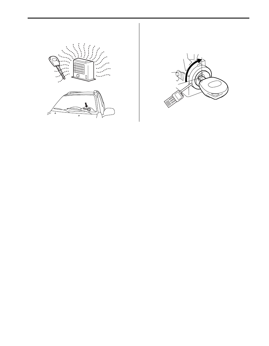
• Do not leave ignition key in a place where 

temperature is high. High temperature may cause 
damage to the transponder built in the ignition key.

• Do not turn ignition switch to ON position by bringing 

radio antenna close to coil antenna. Or, the 
immobilizer control system may detect some 
abnormal condition and prevent the engine from 
starting.

General Description

Immobilizer Control System Introduction

S5JB0BA301001

The immobilizer control system is an anti-theft device that immobilizes the vehicle. It stops the engine from working 
and prevents the vehicle from being stolen. It mainly consists of the following components.
• Engine Control Module (ECM)
• Immobilizer control module (ICM) with the built-in coil antenna
• Ignition key with the built-in transponder
A code called the transponder code is memorized in the transponder. And, the code is registered with ECM. Basically, 
when the ignition switch is turned ON, ECM reads the code by the coil antenna. When that code agrees with the ICM 
registered code, ICM compares the secret code with ECM. When their secret codes agree, the engine can be 
started.If there is no agreement between transponder codes of ICM and ignition key or between secret codes of ICM 
and ECM, ECM stops fuel injection to prevent the engine from starting and turn the injection warning light ON and OFF 
using CAN communication line.

On-Board Diagnostic System Description (Self-diagnosis Function)

S5JB0BA301003

ICM and ECM diagnoses if there is any trouble with the immobilizer control system. The diagnostic information is 
stored as the diagnostic trouble code (DTC) in ICM. To read the diagnostic information, use SUZUKI scan tool 
referring to “Diagnostic Trouble Code (DTC) Check”.
With the ignition switch turned ON (but the engine at stop) regardless of the condition of the engine and emission 
control system, ECM indicates whether there is any trouble with the immobilizer control system or not by either lighting 
ON or flashing ON and OFF the injection warning light.

Injection warning light lights ON:
No trouble exists in the immobilizer control system. (After starting up the engine, the lamp turns OFF.)

Injection warning light flashes ON and OFF:
There is some trouble in the immobilizer control system or in the keyless start system. Its diagnostic information is 
stored in ICM.

I3RH0AA30003-01

I3RH0AA30004-01

10C-3 Immobilizer Control System: 

Schematic and Routing Diagram

Immobilizer Control System Wiring Circuit Diagram

S5JB0BA302001

NOTE
For more details about power supply and ground wire circuits for ECM, BCM, ABS control module, 
ESP

®

 control module and combination meter, refer to “System Circuit Diagram in Section 9A”.


12V

12V

WHT/RED

WHT/BLU

12V

12V

WHT

RED

WHT

RED

BLK/HWT

BLU/BLK

PPL/WHT

BLK

11

8

WHT

RED

E53-13

E53-44

E53-46 E53-42

WHT/RED

WHT/BLU

WHT/BLU

WHT/RED

E03-12

RED

RED

WHT

WHT

E03-6

E03-8 E03-10

G28-8 G28-10

WHT

RED

G31-1

G31-3

G24-3

G24-4

G24-5 G24-6

G24-7

G24-8

1

2

3

4

5

6

7

8

11

9

12

10

13

14

15

1

2

3

4

5

6

7

8

16

2

BLK/RED

G24-1

G24-2

WHT

2

I5JB0BA30003-02

1. Battery

7. ECM

13. From fuse

2. Fuse

8. ABS control module (Vehicle not equipped with 

ESP

®

 system)

14. BCM

3. Ignition switch

9. Junction connector

15. To ECM, TCM, BCM, ABS control module or 

ESP

®

 control module, SDM and 4WD control 

module.

4. Junction block assembly

10. Injection warning light

16. Immobilizer control module (ICM) connector 

(harness side view)

5. Immobilizer control module (ICM)

11. ESP

®

 control module (vehicle equipped with 

ESP

®

 system)

6. Data link connector (DLC)

12. Combination meter

Immobilizer Control System:  10C-4

Component Location

Immobilizer Control System Components Location

S5JB0BA303001

1

2

3

4

5

6

I5JB0BA30001-02

1. ECM

4. Ignition key with keyless entry system

2. Injection warning light (gravity 1 warning light)

5. Ignition key without keyless entry system

3. Immobilizer control module (ICM)

6. Transponder

10C-5 Immobilizer Control System: 

Diagnostic Information and Procedures

Immobilizer Control System Check

S5JB0BA304001

Step

Action

Yes

No

1

Injection warning light ON check
1) Turn ignition switch to ON position.

Does injection warning light (1) come on?

Go to Step 2.

Go to “Injection Warning 
Light Does Not Come 
ON with Ignition Switch 
ON and Engine Stop”.

2

Injection warning light flash check

Does injection warning light flash on and off continuously in 
Step 1?

Go to Step 3.

Go to Step 5.

3

ICM communication check
1) Connect SUZUKI scan tool with turn ignition switch to 

OFF position.

2) Check ICM for DTC referring to “Diagnostic Trouble 

Code (DTC) Check”.

Is communication between ICM and SUZUKI scan tool 
available?

Go to applicable DTC 
diag. flow.

Go to step 4.

4

ICM connector terminal voltage check
1) Check the following terminal voltage on ICM connector 

referring to “Inspection of Immobilizer Control Module 
(ICM) and Its Circuit”
.
• Power circuit
• Ground circuit
• Serial communication line of data link connector

Is each terminal voltage normal?

Substitute a known-
good ICM and recheck.

Repair circuit.

5

Injection warning light remain ON check
1) Check if injection warning light remains ON after engine 

start.

Does injection warning light remain ON after engine start?

Go to “Injection Warning 
Light Remains ON after 
Engine Start”.

Immobilizer control 
system is in good 
condition.

I5JB0BA30002-02


Content   ..  176  177  178  179   ..