Suzuki Grand Vitara JB419. Manual - part 153


  Index      Suzuki     Suzuki Grand Vitara JB419 (with F9Q engine) - service repair manual 2007 year


Search            


Content   ..  151  152  153  154   ..


Suzuki Grand Vitara JB419. Manual - part 153


Wiring Systems:  9A-82

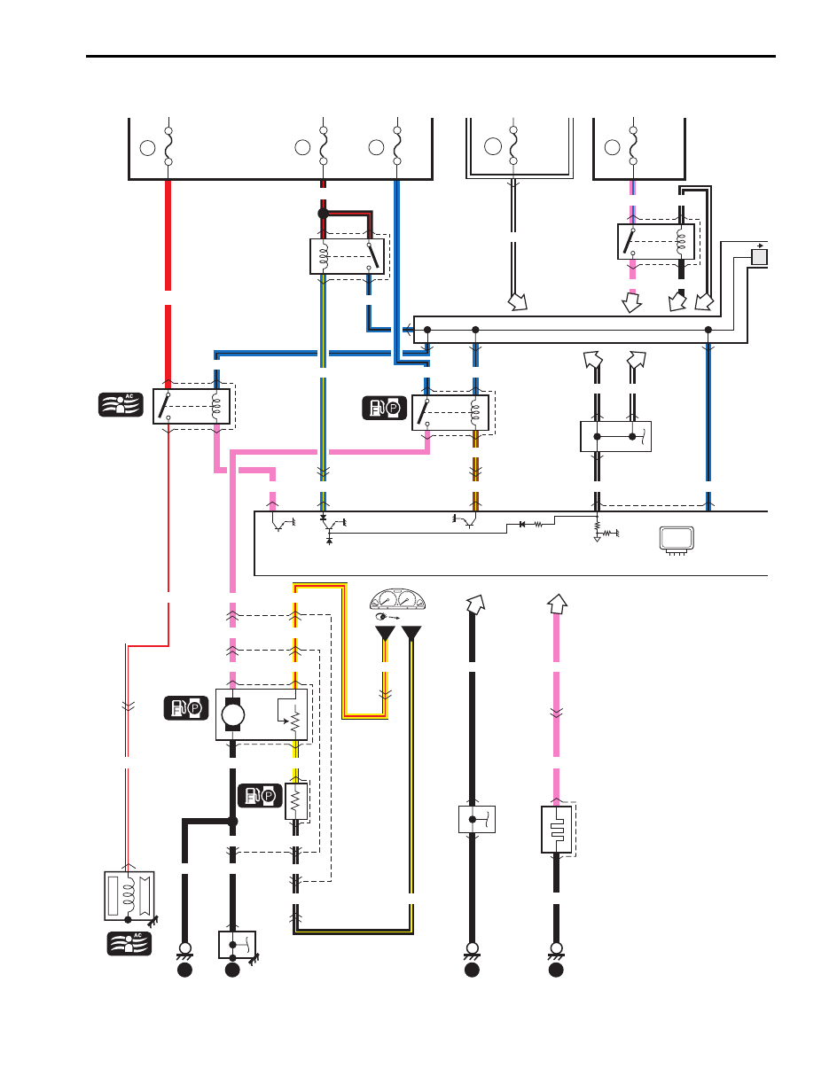
A-5 Engine and A/C Control System Circuit Diagram (DSL)

S5JB0B910E048

1

2

3

4

YEL/RED

E80 

L01

8

G36 

E74

1

15

1

4

PNK

YEL/RED

P

PNK

YEL/RED

YEL/RED

1

3

7

3

21

3

6

YEL/GRN

BLK

BLK/YEL

BLK/YEL

BLK/YEL

BLK/YEL

6

BLK

4

2

1

2

R02

and

fuel gauge

Main  
relay

1

2

BLK/WHT

PNK

BLK

BLK/WHT

PNK/BLU

BLK/WHT BLK/WHT

E62

Weld

splice

Weld

splice

BRN/YEL

BLU/YEL

BRN/YEL

BLK/WHT

IG COIL

J/B

22

30A

FI

12

10A

F/P

BLK/RED

E33

7

8

5

6

20A

39

BLU/YEL

11

15A

A/C

Compressor 

relay

E33

Relay

sub

gauge

RED

Compressor

C17

1

Fuel

heater

relay

E34

1

2

3

5

23

E82

E55 

C35

14

E54 

C34

14

E55 

C35

11

E74 

G36

7

E55 

C35

9

PNK

BLK

C81

Fuel

heater

3

4

1

2

PNK

BLK

PNK

ECM

12

10

11

9

WHT/RED

WHT/RED

BLU/BLK

BLU/BLK

BLU/BLK

BLU/BLK

14

21

11

PNK

E28

1

3

4

2

BLK

BLK

BLU/BLK

2

18

9

30A

F/HTR

Fuse
box
No.2

Fuse box No.2

E66

C86

E66

C85

13

L15

R01

J/C

L22

A

E64

R03

Weld splice

E61

1

"C-1"

BY

YR

I5JB0B910950-01

9A-83 Wiring Systems: 

2

C09

1

C84

C13

C86

C85

ECM

C04

2

1

C05

2

1

C06

2

1

C07

2

1

#2

#1

#3

#4

Turbo

cooling

control

valve

C90

ECT 

sensor

Turbo

cooling

pump

2

PNK/WHT

MAF sensor

5

12

5

12

Rail

pressure

sensor

GRY/GRN

GRY/GRN

1

"A-4"

3

RB

RDTR2

3

Relay

#1

Motor #1

Turbo

cooling

pump

relay

Relay

#2

"A-4"

Motor #2

BR

BY

20

C86

C85

C86

41

1

2

1

23

31

28

30 26

29

25

32 27

11

47

22

24

5

1

4

BLU/BLK

1

2

3

2

9

BLK/BLU

BRN/RED

46

2

BRN/YEL

32

48

23

E55 C35

5

C59

Weld splice

BLU/BLK BLU/WHT

BLU/WHT

BLU/RED

BLU/BLK

WHT/BLU

RED/BLK

RED/BLK

PNK

PNK/BLK

PNK/GRN

PNK/BLU

BLU

3

BLU/BLK

BLU/RED

RED/YEL

RED/YEL

RED/YEL

BLU/WHT

WHT/BLU BLU/WHT

BLU

BLK

BLU/RED

BLU/BLK

RED/BLU

RED/GRN

BLU/BLK

RED/BLK

RED

BLU/BLK

BLU/BLK

6

8

BLU/RED GRY/BLK

GRY/RED

12

6

BLU/BLK

BLK

BLK

BLK

Fuse box
No.2

Fuse box
No.1

10A

T/C P

10

BLU/YEL

BLU/WHT

E29

1

E38

2

1

E58

E34

7

11

7

11

8

6

6

8

RDTR

2

BLU/BLK

8

6

3

1

3

RY

BB

B

18

BLU/BLKBLU/BLK

E30

2

5

7

10

2

5

Relay

#3

1

3

BLU/BLKBLU/YEL

BLU

5

2 4

E31

GRY/RED

GRY/RED

GRY/BLK

GRY/BLK

A/C pressure sensor

E04

13

33

C35 

E55

8

E55 

C35

2

E54 

C34

16

E54 

C34

5

10

13

3

3

1

2

C70

1

M

RHD

BLU/WHT

LHD

40A
30A

Early type
Late type

A
B

A

B

40A
30A

A

B

I5JB0B910951-05

Wiring Systems:  9A-84

ECM

2

Flow

governor

CMP 

sensor

BLK/YEL

BLK/YEL

BLK/YEL WHT/GRN

PNK

YEL/BLK

BLK

3

2

1

2

1

3

C08

C83

C85

C86

15

18

C86

C85

7

39

BLK/GRN

RED/BLK

C59

Weld splice

BLU/BLK

BLU/BLK

BLU/BLK WHT/BLU

BLU

BLU

C85

C86

C85

C86

5

22

Water in

fuel sensor

BLK PNK/GRN

BLK

BLK

1

2

3

C82

13

BLU/BLK

1

C73

2

Up stream

turbine

temperature

sensor

BLU/ORN

BLK/YEL

11

RED/WHT

19

GRY/RED

GRY/RED

GRY/RED

42

29

2

C88

1

Down

stream

temperature

sensor

1

C87

2

Up stream

temperature

sensor

C76

Boost

pressure sensor

3

4

GRY/GRN

45

RED/BLU

14

BLK/RED

12

WHT/BLU

17

WHT/RED

16

1

C89

Diffential

temperature sensor

1

3

C20

CKP sensor

2

1

2

13

14

9

Inlet

throttle valve

PNK/BLK

1

3

2

C75

40

31

PNK/GRN

4

27

BLU/BLK

BLU/YEL

9

50A

56

WHT/BLU

Battery
fuse
box

2

1

C91

C92

50A

54

RED/BLK

15

2

50A

55

RED

Thermo

plug

relay

#1

Thermo

plug

#1

1

3

C93

D08

13

5

2

C71 
D11

1

1

YEL/RED

19

BLU/BLK RED/BLK

BLU/RED

BLU/RED

Thermo

plug

relay

#2

Thermo

plug

#2

1

3

C94

D09

14

5

2

C71 
D11

2

1

YEL/RED

BLU/BLK

RED

BLU/WHT

BLU/WHT

Thermo

plug

relay

#3

Thermo

plug

#3

1

3

C95

D10

15

5

2

C72 
D12

1

1

I5JB0B910952-01

9A-85 Wiring Systems: 

G80

DLC

G20

E74 

G36

28

C34 

E54

4

E54 

C34

8

E74 

G36

29

BLK/YEL

BLK/YEL

4

BLK

15

J/C

G81

31

5

16

WHT

10

WHT/RED

WR

GW

YG

ABS

Cont.M

32

"F-2"

ESP   

Cont.M

"F-3"

26

A

A

A

A

PPL/WHT

PPL/WHT

PPL/WHT

WHT

BLK

BLK

BLK

BLK/YEL

17

3

11

A

WHT/BLU

BLK

J/C

ECM

J/B

15A

DOME

44

20

15A

STOP

38

E66

E66

28

C85

8

BLK

(CAN line)

WHT

GRN/WHT

YEL/GRN

YEL/GRN

GRN

BLU/BLK

WB

7

1

J/C

G76

D

D

J/C

G09

A

10

G03

E82

15

BLK

7

BLK

8

BLK

9

Weld

splice

E65

J/C

G82

A

A

A

Weld

splice

E61

WHT

RED

R

W

"A-8"

14

6

BCM

E67

Brake

light

switch

1

2

3

4

(CAN line)

16

G05 

E78

14

13

12

E66

BLU/BLK

BLU/BLK

20

17

BLK/WHT

LT GRN

23

BLK/YEL

BLK/WHT

LT GRN

BLK/YEL

BB

E78 

G05

MAIN

RESUME/

ACCEL

SET/ 

COAST

CANCEL

G54

12

Steering

switch

(Auto

cruise)

11

6

10

IF EQPD

EGR

stepper

motor

C10

BLU

RED

LT GRN

6

4

3

1

2

C86

25

26

20

43

C85

11

LT GRN/RED

LT GRN/BLK

M

R

I5JB0B910953-04


Content   ..  151  152  153  154   ..