Suzuki Grand Vitara JB419. Manual - part 49


  Index      Suzuki     Suzuki Grand Vitara JB419 (with F9Q engine) - service repair manual 2007 year


Search            


Content   ..  47  48  49  50   ..


Suzuki Grand Vitara JB419. Manual - part 49


Engine Mechanical:  1D-42

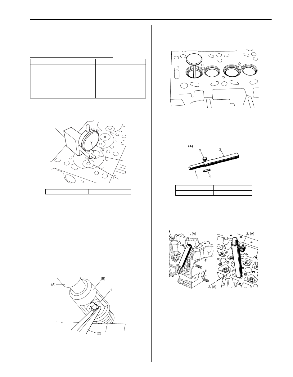
Valve and Cylinder Head Assembly Inspection

S5JB0B1406063

Cylinder Head Assembly Specifications (for 
Reference)

Valve and cylinder head specification

Special tool
(A):  09910–26510 

Valve and Cylinder Head Disassembly and 
Reassembly

S5JB0B1406064

Disassembly

1) Using special tool (A) and (B), compress valve 

spring, and remove valve cotters (1) also by using 
special tool (C).

Special tool
(A):  09916–19030 
(B):  09916–14521 
(C):  09916–84511 

2) Release special tool and remove spring retainer, 

valve spring and spring seat from cylinder head.

3) Remove valve from combustion chamber side.

4) Measure stem seal height as follows in order to 

install stem seal in specified position.

Special tool
(A):  09917–96530

a) Fit pushrod (1) of special tool on valve stem seal.
b) Fit guide tube (2) of special tool over pushrod (1) 

until guide tube comes into contact with cylinder 
head, and lock pushrod with screw (3).

c) Remove special tool.

Item

Specification

Valve protrusion 

(valve closed)

– 0.03 to 0.21 mm 

(– 0.0011 to 0.0082 in.)

Max. valve lift

Intake valve

8.866 mm 

(0.34895 in.)

Exhaust valve

10.344 mm 

(0.40724 in.)

1. Intake valve

2. Exhaust valve

(A)

1

2

I5JB0B140080-01

I5JB0B140081-01

1. Pushrod

3. Screw

2. Tube

4. Fitting

I5JB0B140082-01

I5JB0B140083-02

I5JB0B140084-01

1D-43 Engine Mechanical: 

5) Remove stem seal (1) from valve guide using special 

tool.

Special tool
(A):  09916–48110 

Reassembly

1) Apply engine oil to valve guide bore and valve stem, 

and install valve (1) to valve guide.

2) Install valve stem seal using special tool (A) as 

follows.

Special tool
(A):  09917–96530

a) Install fitting (2) to valve stem in order to prevent 

stem seal from damage, and install stem seal (1) 
to valve stem.

NOTE

• Be sure to remove special tool after 

installing stem seal.

• Do not lubricate the valve stem seal before 

fitting.


b) Place pushrod (1) which is measured stem seal 

height in removal.

c) Press into stem seal tapping top of pushrod (1) 

by hand until tube (2) touches cylinder head.

CAUTION

!


Do not tap pushrod (1) by hammer.It may 
result in misinstalling of stem seal and 
damage of special tool.


1. Pushrod

3. Screw

2. Tube

4. Fitting

(A)

1

I5JB0B140085-01

I5JB0B140086-01

I5JB0B140083-02

I5JB0B140134-01

I5JB0B140087-01

Engine Mechanical:  1D-44

3) Install spring seat, valve spring and spring retainer.
4) Using special tool (A) and (B), compress valve 

spring. And, fit two valve cotters (1) into groove of 
valve stem using special tool (C) as shown in figure.

Special tool
(A):  09916–19030 
(B):  09916–14521 
(C):  09916–84511 

Valves and Valve Guides Inspection

S5JB0B1406027

Valve Guide
Valve stem-to-guide clearance
Using a micrometer and bore gauge, take diameter readings on valve stems and guides to check stem-to-guide 
clearance.
Be sure to take reading at more than one place along the length of each stem and guide.
If clearance is out specification, replace valve and valve guide.

Valve stem diameter [A]
In: 6.974 – 6.996 mm (0.27457 – 0.27543 in.)
Ex: 6.960 – 6.982 mm (0.27402 – 0.27488 in.)

Valve guide bore [B]
In: 7.000 – 7.022 mm (0.27560 – 0.27645 in.)
Ex: 7.000 – 7.022 mm (0.27560 – 0.27645 in.)

Stem-to-guide clearance
In: 0.004 – 0.048 mm (0.00016 – 0.00188 in.)
Ex: 0.018 – 0.062 mm (0.00071 – 0.00244 in.)

I5JB0B140081-01

I4RS0B140016-01

1D-45 Engine Mechanical: 

Valve
Visual inspection
• Remove all carbon from valves.
• Inspect each valve for wear, burn or distortion at its 

face and stem end, as necessary, replace it.

• Inspect valve stem end face for pitting and wear. If 

pitting or wear is found there, valve stem end may be 
resurfaced, but not too much to grind off its chamber. 
When it is worn out too much that its chamber is gone, 
replace valve.

Valve and Related Parts Specifications (for 
Reference)

Valve

Valve seat

Valve guide

Item

Specification

Valve length “a”

Intake valve

110.79 – 111.19 mm 

(4.3619 – 4.3775 in.)

Exhaust valve

110.59 – 110.99 mm 

(4.3540 – 4.3696 in.)

Valve head 

diameter “b”

Intake valve

35.20 – 35.45 mm

(1.3859 – 1.3956 in.)

Exhaust valve

32.50 – 32.75 mm

(1.2796 – 1.2893 in.)

Valve face angle “c” 

90

°

I2RH01140135-01

“b”

“a”

“c”

I5JB0B140088-02

Item

Specification

Valve seat width “a” 

1.8 mm

(0.071 in.)

Valve seat angle “b”

89.5

°

Valve seat 

outside 

diameter “c”

Intake valve

36.967 – 36.983 mm

(1.45540 – 1.45602 in.)

Exhaust valve

33.589 – 33.605 mm

(1.32240 – 1.32303 in.)

Item

Specification

Valve guide bore “a” 

(supply parts)

6.30 – 6.42 mm

(0.2481 – 0.2527 in.)

Valve guide length “b”

38.10 – 38.40 mm

(1.5000 – 1.5118 in.)

Valve guide outside 

diameter “c”

12.050 – 12.068 mm

(0.47441 – 0.47511 in.)

I5JB0B140089-02

I5JB0B140090-01


Content   ..  47  48  49  50   ..