Suzuki Grand Vitara JB416 / JB420 (ESP model). Manual - part 58
4E-26 ABS:
DTC C1061: Pump Motor and/or Motor Driver Circuit
S5JB0E4504017
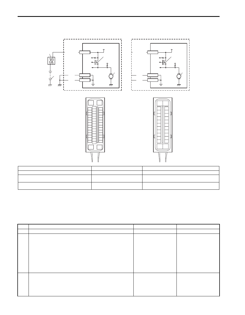
Wiring Diagram
DTC Detecting Condition
The ABS (ESP
®) control module monitors the voltage at monitor terminal of pump motor circuit constantly with the
ignition switch turned ON. It sets this DTC when the voltage at the monitor terminal does not become high / low
according to ON/OFF commands to the motor driver (transistor) of the module (does not follow these commands).
DTC Troubleshooting
4
5
1
2
WHT/BLU
3
12V
M
12V
BLK
BLK
E53-16
E53-47
E53-32
4
6
WHT/BLU
3
12V
M
12V
BLK
BLK
E03-13
E03-26
E03-1
[D]
E03
15
16
17
18
19
20
21
22
23
24
25
2
3
4
5
6
7
8
9
10
11
12
1
13
14
26
[C]
E53
16
1
15
2
3
4
5
6
7
8
9
10
11
12
13
14
17
18
19
20
21
22
23
24
25
26
27
28
29
30
31
32
33
34
35
36
37
38
39
40
41
42
43
44
45
46
47
[B]
[A]
I6JB01450010-01
[A]: With ESP
®
1. Battery
5. ESP
® hydraulic unit / control module assembly
[B]: Without ESP
®
2. Main fuse box
6. ABS hydraulic unit / control module assembly
[C]: ESP
® control module connector (viewed from
terminal side)
3. Pump motor driver (transistor)
[D]: ABS control module connector (viewed from
terminal side)
4. Pump motor
Step
Action
Yes
No
1
Was “ABS Check” performed?
Go to Step 2.
2
1) Turn Ignition switch to OFF position.
2) Disconnect ABS (ESP
®) control module connector.
3) Check for proper connection to ABS (ESP
®) control
module connector at terminal “E03-1” (or “E53-32”).
4) If OK, then measure voltage between terminal “E03-1”
(or “E53-32”) of module connector and body ground.
Is it 10 – 14 V?
Go to Step 3.
“WHT/BLU” circuit
open.
3
Measure resistance between terminal “E03-13” and “E03-
26” (or “E53-16” and “E53-47”) of ABS (ESP
®) hydraulic unit
/ control module connector and vehicle body ground.
Is resistance less than 1
Ω
?
Substitute a known-
good ABS (ESP
®)
hydraulic unit / control
module assembly and
recheck.
Ground circuit for ABS
(ESP
®) control module
open or high resistance.