Suzuki Grand Vitara JB416 / JB420 (ESP model). Manual - part 33
3C-27 Transfer: Motor-Shift Type (Transfer with Shift Actuator)
Transfer Position Indicator Remains ON Steady at Ignition Switch ON
S5JB0E3314013
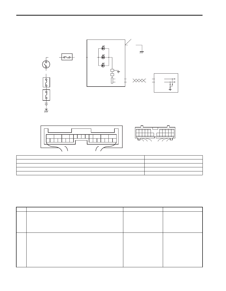
Wiring Diagram
Circuit Description
Transfer position indicator operates according to the signal from 4WD control module. If the transfer control system is
in good condition, transfer position indicator light up for 2 seconds when ignition switch is turned to ON position, and
then turned to OFF position. If an abnormality is detected in the system, transfer position indicator remains lighting.
Troubleshooting
E91-22
E91-23
RED
WHT
RED
WHT
G28-10
G28-8
1
2
G28-13
PPL/RED
BLK
WHT/GRN
BLK/YEL
8
G28-15
4
6
7
5
3
1
2
3
4
5
6
7
8
9
10
11
17
1615141312
2221201918
[B]
1
2
3
4
5
6
7
8
9
10
11
12
13
14
15
16
17
18
19
20
21
22
23
24
25
26
[A]
I5JB0A332015-03
[A]: 4WD control module connector “E91” (viewed from harness side)
4. 4L indicator
[B]: Combination meter connector (viewed from harness side)
5. N indicator
1. 4WD control module
6. Junction block assembly
2. Combination meter
7. “METER” fuse
3. Differential lock indicator
8. Ignition switch
Step
Action
Yes
No
1
Check DTC
1) Check DTC referring to “DTC Check: Motor-Shift Type
(Transfer with Shift Actuator)”.
Is there any DTC(s)?
Perform DTC flow to
repair and retry.
Go to Step 2.
2
CAN communication circuit check
1) Check CAN communication circuit between combination
meter and 4WD control module referring to “DTC U1073:
Control Module Communication Bus Off: Motor-Shift
Type (Transfer with Shift Actuator)”.
Is CAN communication circuit in good condition?
Substitute a known-
good combination meter
and recheck. If transfer
position indicator still
remains off, substitute a
known-good 4WD
control module and
recheck.
Repair or replace.