Suzuki Grand Vitara JB627. Manual - part 313
8B-78 Air Bag System:
NOTE
Upon completion of inspection and repair work, perform the following items.
• Reconnect all air bag system components, ensure all components are properly mounted.
• Clear DTCs referring to “DTC Clearance”, if any.
• Repeat “Air Bag Diagnostic System Check” to confirm that the trouble has been corrected.
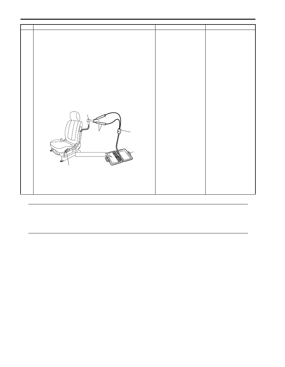
3
1) With ignition switch OFF, disconnect special tools (B)
and (C) then reconnect connector “L25” or “L30”.
2) Disconnect side-air bag (inflator) module connector
“Q02” or “Q03” from side-air bag (inflator) module.
3) Check proper connection to side-air bag (inflator)
module at terminal in connector.
4) If OK, then connect special tools (A), (B) and (C) to side-
air bag (inflator) connector.
Special tool
(A): 09932–76010
(B): 09932–75010
(D): 09932–78310
5) Check SDM DTC.
With ignition switch ON, is DTC B1322 or B1326 still
indicated?
DTC B1322: Repair
short from “GRY/RED”
wire circuit to “GRY”
wire circuit in seat
harness or from “GRY/
RED” or “GRY” wire
circuit to other wire
circuit.
DTC B1326: Repair
short from “BRN/WHT”
wire circuit to “BRN”
wire circuit in seat
harness or from “BRN/
WHT” or “BRN” wire
circuit to other wire
circuit.
Replace side-air bag
(inflator) module
referring to “Side-Air
Bag (Inflator) Module
Removal and
Installation”.
Step
Action
Yes
No
“L25”, “L30”
STEERING WHEEL
(B)
(D)
(A)
“Q02”, “Q03”
I5JB0A820046-02