Suzuki Grand Vitara JB627. Manual - part 284
7B-52 Air Conditioning System:
DTC B1551: Serial Communication Circuit Malfunction
S6JB0B7204024
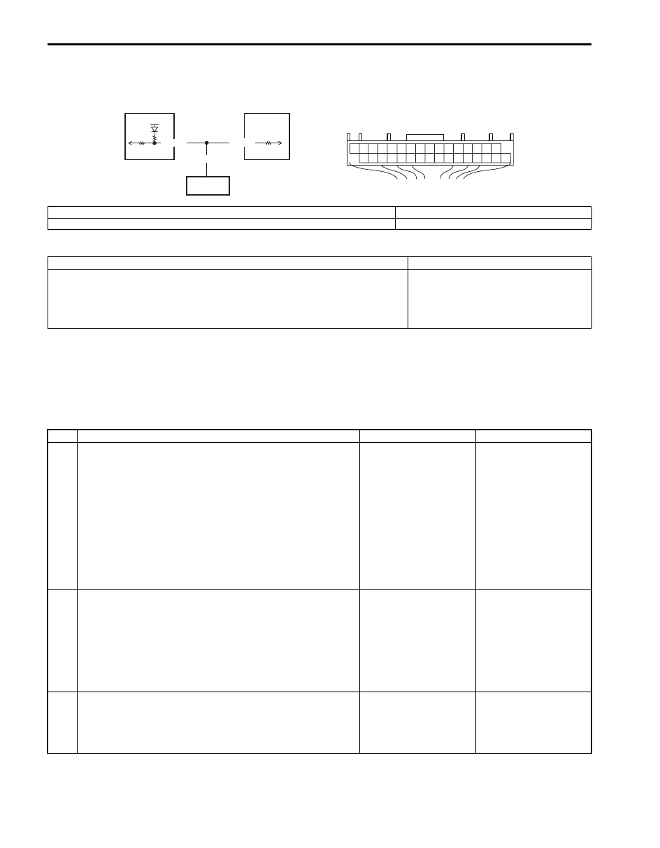
Wiring Diagram
DTC Detecting Condition and Trouble Area
DTC Confirmation Procedure
1) Connect scan tool to DLC with ignition switch turned OFF.
2) Turn ON ignition switch and clear DTC using scan tool.
3) Check DTC.
DTC Troubleshooting
5V
G52-10
G30-5
YEL/RED
[A]
2
1
3
10
I5JB0A720029-01
[A]: HVAC control module connector “G52” (harness side view)
2. BCM
1. HVAC control module
3. Information display
DTC detecting condition
Trouble area
Serial communication signal is more than or less than specified value for
specified time continuously.
• Serial communication line of BCM
• BCM
• Information display
• HVAC control module
Step
Action
Yes
No
1
DTC check
1) Connect scan tool to DLC with ignition switch turned
OFF.
2) Turn ignition switch ON and clear DTC referring to “DTC
3) Disconnect connector from information display with
ignition switch turned OFF.
4) Turn ignition switch ON and check DTC referring to
Is there DTC B1551?
Go to Step 2.
Information display
faulty.
2
Wire harness check
1) Disconnect connectors from BCM and HVAC control
module.
2) Measure resistance between “G30-5” terminal of BCM
connector and “G52-10” terminal of HVAC control
module connector.
Is resistance below 5
Ω
?
Go to Step 3.
“YEL/RED” wire open or
high resistance circuit.
3
Wire harness check
1) Measure resistance between “G52-10” terminal of HVAC
control module connector and vehicle body ground.
Is resistance infinity?
Go to Step 4.
“YEL/RED” wire shorted
to ground circuit.