Suzuki Grand Vitara JB627. Manual - part 229


  Index      Suzuki     Suzuki Grand Vitara JB627 - service repair manual


Search            


Content   ..  227  228  229  230   ..


Suzuki Grand Vitara JB627. Manual - part 229


5A-100 Automatic Transmission/Transaxle: 

Transmission Fluid Temperature Sensor 
Removal and Installation

S6JB0B5106023

Removal

1) Disconnect negative cable at battery.
2) Pull out fluid level gauge and lift up vehicle.
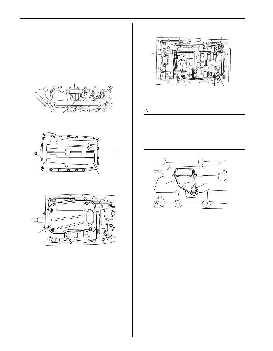
3) Remove exhaust No.1 pipe (1).
4) Remove drain plug (2) and drain A/T fluid.
5) Install drain plug (2).

6) Remove A/T oil pan (1).

7) Remove A/T oil strainer (1).

8) Remove transmission fluid temperature sensor A (8) 

and B (9) (if equipped).

9) Disconnect shift solenoid-A connector (1), shift 

solenoid-B connector (2), shift solenoid-E connector 
(3), TCC solenoid connector (4), Pressure control 
solenoid-A connector (5), Pressure control solenoid-
B connector (6) and Pressure control solenoid-C 
connector (7).

10) Remove solenoid valves.

11) After removing bolt (1) pull out transmission wire 

connector (2) from transmission case.

CAUTION

!


When pulling transmission wire harness out 
of transmission case, take care not to 
damage connectors and transmission fluid 
temperature sensors at narrow exist of case. 
Careless sensor treatment might cause 
sensor malfunction.


Installation
Remove removal procedure to install transmission fluid 
temperature sensor, noting the following points.
• For details of solenoid valves and their connectors 

installation, refer to “Automatic Transmission Unit 
Assembly”
. Use new O-ring.

• For details of A/T oil pan installation, refer to 

“Automatic Transmission Unit Assembly”.

• Tighten exhaust No.1 pipe bolts & nuts.
• Fill A/T fluid and check fluid level according to 

procedure described in “A/T Fluid Change”.

• Check for fluid leakage after warming up A/T.

2

1

I6JB01510026-01

1

I4JA01512025-01

1

I4JA01512026-01

7

8

9

5

3

1

2

4

6

I6JB0B510008-01

2

1

I4JA01512070-01

Automatic Transmission/Transaxle:  5A-101

Transmission Fluid Temperature Sensor 
Inspection

S6JB0B5106024

Immerse transmission fluid temperature sensor A (1) 
and B (3) (if equipped) in water or oil. Check 
transmission fluid temperature sensor A or B resistance 
between terminals of connector. Thus make sure its 
resistance decreases as temperature rises.

Transmission fluid temperature sensor A and B 
resistance
10 

°C (50 °F): 6.445 k

25 

°C (77 °F): 3.5 k

110 

°C (230 °F): 0.247 k

Transmission Control Module (TCM) Removal 
and Installation

S6JB0B5106025

CAUTION

!


TCM consists of highly precise parts, so 
when handling it, be careful not to expose it 
to excessive shock.


Removal

1) Disconnect negative cable at battery.
2) Disable air bag system.

Refer to “Disabling Air Bag System in Section 8B”.

3) Remove glove box.
4) Disconnect connectors from TCM (1).
5) Remove TCM with 4WD control module (2) by 

removing its nuts, and then separate TCM and 4WD 
control module.

Installation
Reverse removal procedure noting the following points.
• Connect TCM connectors securely.
• Be sure to enable air bag system after TCM is back in 

place. Refer to “Enabling Air Bag System in Section 
8B”.


1

2

3

4

5

6

7

8

9

10

11

12

13

14

15

1

2

3

4

5

6

7

8

9

10

11

12

13

14

15

A

B

1

3

2

I6JB0B510010-01

1

2

I6JB01510027-01

5A-102 Automatic Transmission/Transaxle: 

A/T Relay Inspection

S6JB0B5106026

1) Disconnect negative cable at battery.
2) Remove integration relay No.2 (1) from fuse box 

No.2 (2).

3) Check that there is no continuity between terminals 

“E41-1” and “E38-8”.
If there is continuity, replace relay.

4) Connect battery positive (+) terminal to terminal 

“E38-6” of relay. Connect battery negative (–) 
terminal to terminal “E38-7” of relay. Check for 
continuity between terminal “E41-1” and “E38-8”. If 
there is no continuity when relay is connected to the 
battery, replace integration relay No.2.

Oil Cooler Pipes Removal and Installation

S6JB0B5106027

Removal

1) Lift up vehicle.
2) Make sure to wash dirt off from around pipe joints.
3) When engine is cool, loosen oil cooler pipe union 

bolts with oil outlet union locked and remove oil 
cooler pipes (1) from oil outlet union and hoses.

NOTE
To avoid fluid leakage, plug open ends of oil 
outlet unions and hoses right after they are 
disconnected.


Installation

1) Use new union gaskets and connect oil cooler pipes 

to oil outlet unions.

2) Connect hoses to pipes and clamp them securely.
3) Tighten union bolts (2) to specified torque with oil 

outlet union locked.

Tightening torque
Oil cooler pipe union bolt (a):  25 N·m (2.5 kgf-m, 
18.0 lb-ft)

4) Tighten pipe clamp bolt (3) with specified torque.

Tightening torque
Pipe clamp bolt (b):  10 N·m (1.0 kgf-m, 7.5 lb-ft)

5) Check A/T fluid level according to procedure 

described in “A/T Fluid Change”.

6) Check for fluid leakage after warming up A/T.

2

1

I5JB0A130031-02

1

1

2

3

4

5

6

7

8

1

2

3

4

5

6

7

8

E41

E41

E41

E37

E38

“E38-6”

“E41-1”

“E38-7”

“E38-8”

I5JB0A510159-01

3, (b)

2, (a)

1

I6JB01510028-01

Automatic Transmission/Transaxle:  5A-103

Automatic Transmission Unit Components

S6JB0B5106028

22

(e)

(f)

31

30

8

4

3

5

6

18

25

23

24

20

27

(f)

28

(f)

29

(a)

2

(a)

1

(g)

34

16

9

10

19

12

17

(b)

7

(a)

13

(d)

(f)

26

(d)

(c)

15

(c)

14

21

(c)

11

32

15

I6JB01510030-01

1. Torque converter mounting 

bolt No.1
: After tightening torque 
converter mounting bolt No.1, 
tighten torque converter 
mounting bolt No.2.

11. Transmission to engine bolt 

No.1

21. Transmission range

31. Starting motor bolt

2. Torque converter mounting 

bolt No.2

12. Exhaust manifold left bracket 

bolt

22. Engine harness

32. Transmission

3. Drive plate

13. Transmission to engine bolt 

No.2

23. Transfer

33. Drive plate bolt

4. Torque converter

14. CKP sensor

24. Transfer to transmission bolt

: 65 N

⋅m (6.5 kgf-m, 47.0 lb-ft)

5. Oil cooler hose

15. Engine to transmission nut

25. Engine rear mounting

: 10 N

⋅m (1.0 kgf-m, 7.5 lb-ft)

6. Clamp

16. Exhaust manifold right 

bracket

26. Engine rear mounting bolt

: 80 N

⋅m (8.0 kgf-m, 58.0 lb-ft)

7. Drive plate cover bolt

17. Exhaust manifold right 

bracket bolt

27. Engine rear mounting bracket

: 30 N

⋅m (3.0 kgf-m, 22.0 lb-ft)


Content   ..  227  228  229  230   ..