Suzuki Grand Vitara JB627. Manual - part 160
3C-44 Transfer:
DTC C1246: Clutch Pedal Position (CPP) Switch Circuit Short
S6JB0B3304025
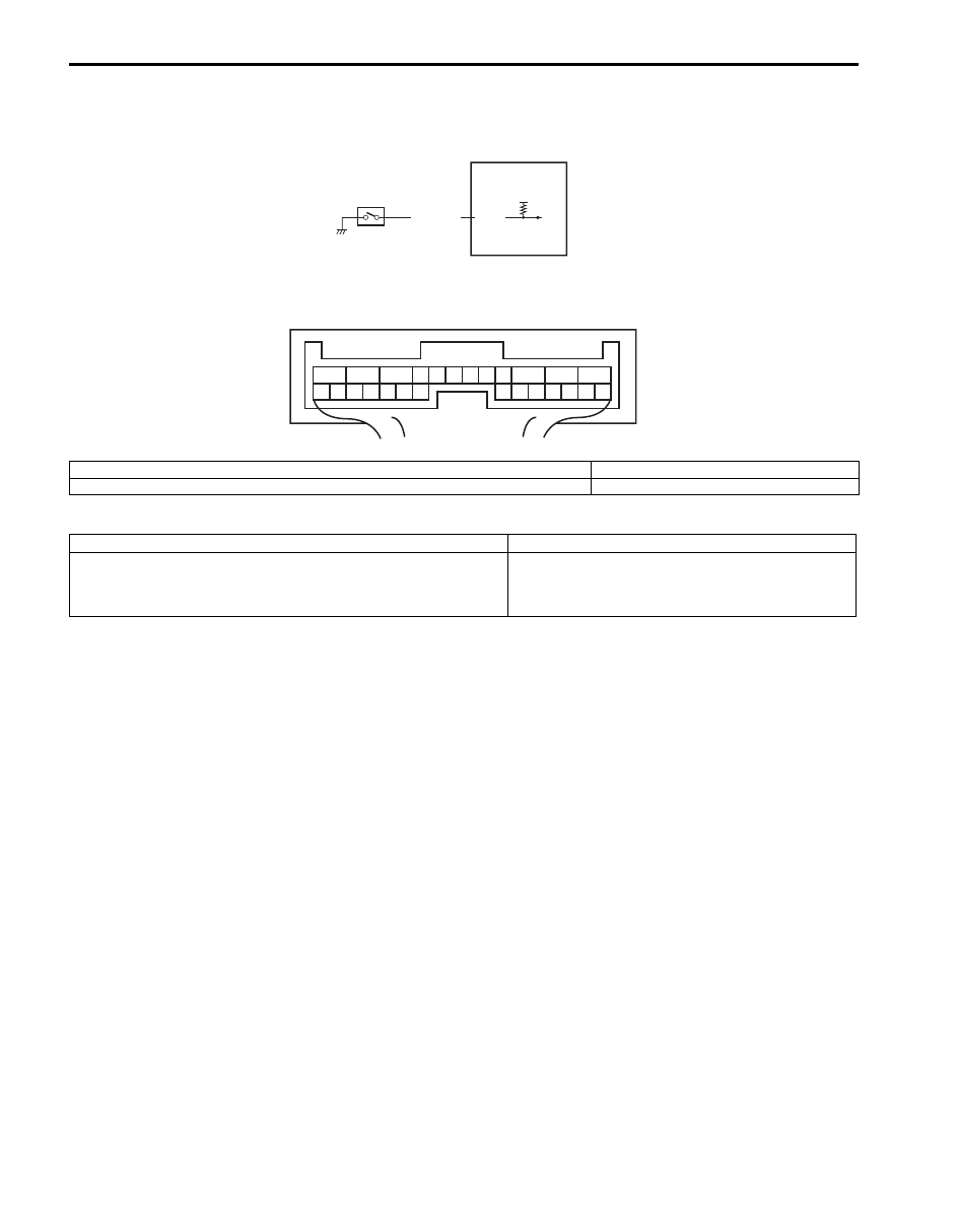
Wiring Diagram
DTC Detecting Condition and Trouble Area
DTC Confirmation Procedure
1) Clear DTC using scan tool.
2) Start engine and drive vehicle at 50 km/h (31 mile/h) or more vehicle speed at least for 1 min.
3) Stop vehicle and check DTC.
12V
E91-7
BLK/ORN
1
2
1
2
3
4
5
6
7
8
9
10
11
12
13
14
15
16
17
18
19
20
21
22
23
24
25
26
[A]
I5JB0A332020-01
[A]: 4WD control module connector “E91” (viewed from harness side)
2. 4WD control module
1. CPP switch
DTC detecting condition
Trouble area
CPP switch signal is input when vehicle speed is 30 km/h (19
mph).
• CPP switch
• CPP switch circuit
• 4WD control module