Suzuki Grand Vitara JB627. Manual - part 88


  Index      Suzuki     Suzuki Grand Vitara JB627 - service repair manual


Search            


Content   ..  86  87  88  89   ..


Suzuki Grand Vitara JB627. Manual - part 88


1D-33 Engine Mechanical: 

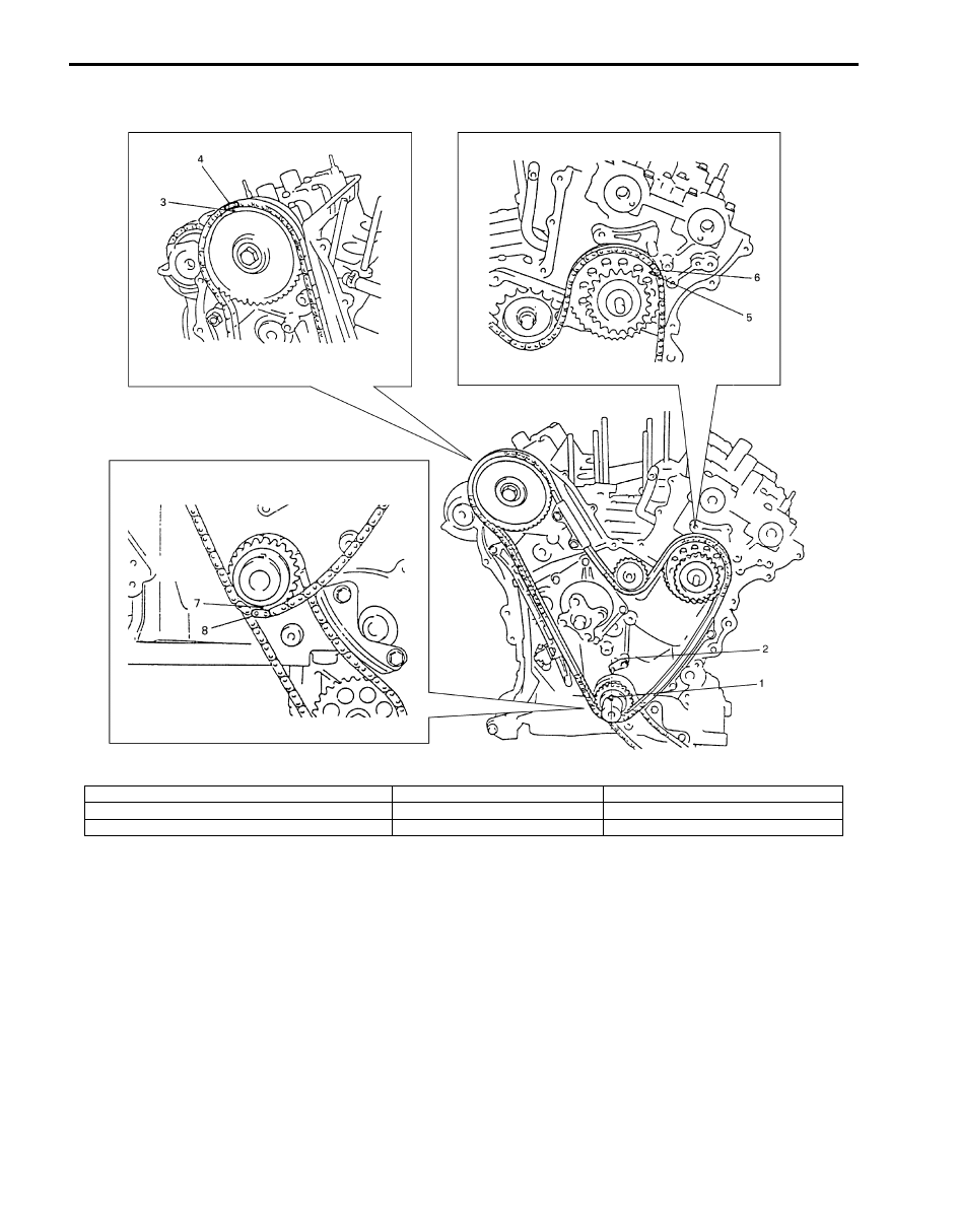
17) Check each aligned timing marks as shown in figure.

18) Install LH (No.1) bank 2nd timing chain. Refer to “LH (No.1) Bank 2nd Timing Chain and Chain Tensioner Removal 

and Installation”.

19) Install timing chain cover. Refer to “Timing Chain Cover Removal and Installation”.
20) Install oil pans referring to “Oil Pan and Oil Pump Strainer Removal and Installation in Section 1E”.
21) Install cylinder head covers referring to “Cylinder Head Covers Removal and Installation”.
22) Install intake manifold, intake collector and electric throttle body assembly referring to “Intake Collector and Intake 

Manifold Removal and Installation” and “Electric Throttle Body Assembly Removal and Installation”.

23) Install engine assembly to vehicle referring to “Engine Assembly Removal and Installation”.

I6JB01140062-01

1. Crank timing pulley key

4. Silver plate (LH) of 1st timing chain

7. Match mark of crankshaft timing sprocket

2. Oil jet

5. Match mark of idler sprocket No.2

8. Yellow plate of 1st timing chain

3. Match mark of RH (No.2) bank 1st timing chain sprocket

6. Silver plate (LH) of 1st timing chain

Engine Mechanical:  1D-34

1st Timing Chain and Chain Tensioner 
Inspection

S6JB0B1406023

Timing Chain Guides No.1 and No.2
Check shoe for excessive wear or damage.
If any malfunction is found, replace it.

Timing Chain Tensioner
Check shoe (1) for wear or damage.
If any malfunction is found, replace it.

1st Timing Chain Crankshaft Sprocket
Check teeth of sprocket for wear or damage.
If any malfunction is found, replace it.

RH (No.2) Bank 1st Timing Chain Intake Camshaft 
Sprocket
Check teeth of sprocket for wear or damage.
If any malfunction is found, replace it.

Idler Sprocket No.1
Check teeth of sprocket for wear or damage.
If any malfunction is found, replace it.

Idler Sprocket No.2
Check teeth of sprocket for wear or damage.
If any malfunction is found, replace it.

1st Timing Chain
Check timing chain for wear or damage.
If any malfunction is found, replace it.

Timing Chain Tensioner Adjuster No.1
Check that latch (1) and tooth surface (2) are free from 
damage and latch functions properly.
If any malfunction is found, replace it.

1. Timing chain guide No.1

2. Timing chain guide No.2

2

1

I6JB01140063-01

IYSQ01143061-01

I6JB01140064-01

I6JB01140065-01

1. Bearing

1. Bush

1

I6JB01140066-01

1

I6JB01140067-01

IYSQ01143066-01

1

2

I6JB01140068-01

1D-35 Engine Mechanical: 

RH (No.2) Bank 2nd Timing Chain and Chain Tensioner Components

S6JB0B1406024

I6JB01140069-01

1. RH (No.2) bank 2nd timing chain

6. RH (No.2) bank intake camshaft

11. Timing chain tensioner adjuster No.2 bolt

2. Timing chain tensioner adjuster No.2

7. RH (No.2) bank exhaust camshaft 

housing

12. Camshaft housing bolt

3. RH (No.2) bank exhaust camshaft 

sprocket

8. RH (No.2) bank intake camshaft 

housing

: Apply engine oil to sliding surface of each part.

4. RH (No.2) bank intake camshaft 

sprocket

9. Timing chain guide No.3

: Tighten 11 N

⋅m (1.1 kgf-m, 8.0 lb-ft) by the specified procedure.

5. RH (No.2) bank exhaust camshaft

10. Timing chain guide No.3 bolt

Engine Mechanical:  1D-36

RH (No.2) Bank 2nd Timing Chain and Chain 
Tensioner Removal and Installation

S6JB0B1406025

1) Remove engine assembly from vehicle. Refer to 

“Engine Assembly Removal and Installation”.

2) Remove timing chain cover. Refer to “Timing Chain 

Cover Removal and Installation”.

3) For reinstallation of timing chain, align 12 timing 

marks as shown in figure by turning crankshaft.

4) Remove LH (No.1) bank 2nd timing chain. Refer to 

“LH (No.1) Bank 2nd Timing Chain and Chain 
Tensioner Removal and Installation”.

5) Remove 1st timing chain. Refer to “1st Timing Chain 

and Chain Tensioner Removal and Installation”.

6) Remove timing chain guide No.3 referring to “RH 

(No.2) Bank 2nd Timing Chain and Chain Tensioner 
Components”.

7) Loosen camshaft housing bolts in such order (“1” – 

“17”) as indicated in figure and remove them.

8) Remove camshaft housings.

9) Remove RH (No.2) bank intake camshaft, RH (No.2) 

bank exhaust camshaft, and RH (No.2) bank 2nd 
timing chain as a set referring to “RH (No.2) Bank 
2nd Timing Chain and Chain Tensioner 
Components”.

10) Remove timing chain tensioner adjuster No.2 

referring to “RH (No.2) Bank 2nd Timing Chain and 
Chain Tensioner Components”
.

Installation

1) Check timing mark on crankshaft as shown in figure.

2) Apply oil to timing chain tensioner adjuster No.2 (1).
3) Install timing chain tensioner adjuster No.2 (1).

Tightening torque
Timing chain tensioner adjuster No.2 bolt (a):  11 
N·m (1.1 kgf-m, 8.0 lb-ft)

4) Apply oil to sliding surface of each camshafts and 

camshaft journals.

5) Install RH (No.2) bank 2nd timing chain by aligning 

match marks on yellow plates (1) of RH (No.2) bank 
2nd timing chain, RH (No.2) bank 2nd timing chain 
intake camshaft sprocket and RH (No.2) bank 2nd 
timing chain exhaust camshaft sprocket as shown in 
figure.

I6JB01140070-01

I6JB01140071-01

1. Crank timing pulley key

2. Oil jet

2. Water pump

3. Engine front side

2. Match mark of RH (No.2) bank 2nd timing chain exhaust camshaft sprocket
3. Match mark of RH (No.2) bank 2nd timing chain intake camshaft sprocket

2

1

I6JB01140072-01

I6JB01140073-01

IYSQ01143088-01


Content   ..  86  87  88  89   ..