Suzuki Grand Vitara JB627. Manual - part 73


  Index      Suzuki     Suzuki Grand Vitara JB627 - service repair manual


Search            


Content   ..  71  72  73  74   ..


Suzuki Grand Vitara JB627. Manual - part 73


1A-241 Engine General Information and Diagnosis: 
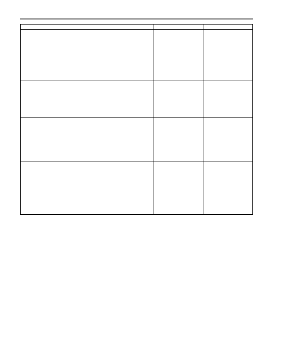
5

Radiator cooling fan control check
1) Disconnect connector from radiator cooling fan motor 

No.2 with ignition switch turned OFF.

2) Turn ignition switch ON.
3) Measure voltage between “BLU” wire terminal of radiator 

cooling fan relay No.3 connector and vehicle body 
ground.

Is voltage 0 V?

Go to Step 6.

“BLU” wire is shorted to 
other circuit.

6

Wire circuit check
1) Measure resistance between “BLU” wire terminals of 

radiator cooling fan relay No.3 connector and radiator 
cooling fan motor No.2 connector with ignition switch 
turned OFF.

Is resistance below 3 

?

Go to Step 7.

“BLU” wire is open or 
high resistances.

7

Wire circuit check
1) Disconnect radiator cooling fan relay No.2 from relay 

box.

2) Measure resistance between “BLK” wire terminal of 

radiator cooling fan relay No.2 connector and vehicle 
body ground.

Is resistance below 3 

?

Go to Step 8.

“BLK” wire is open 
circuit.

8

Radiator cooling fan relay check
1) Check radiator cooling fan relay referring to “Radiator 

Cooling Fan Relay Inspection in Section 1F”.

Is it in good condition?

Go to Step 9.

Replace radiator cooling 
fan relay.

9

Radiator cooling fan motor check
1) Check radiator cooling fan motor referring to “Radiator 

Cooling Fan Motor On-Vehicle Inspection in Section 1F”.

Is it in good condition?

Substitute a known 
good ECM and recheck.

Replace radiator cooling 
fan motor.

Step

Action

Yes

No

Engine General Information and Diagnosis:  1A-242

Repair Instructions

Idle Speed and IAC Throttle Valve Opening 
Inspection

S6JB0B1106001

Before idle speed check, make sure of the following.
• Lead wires and hoses of electronic fuel injection and 

engine and emission control systems are connected 
securely.

• Valve lash is checked according to maintenance 

schedule.

• Ignition timing is within specification.
• ECT sensor performance is in good condition.
• All accessories (wipers, heater, lights, A/C, etc.) are 

out of service.

• Air cleaner has been properly installed and is in good 

condition.

• No abnormal air drawn in from air intake system.
After all items are confirmed, check idle speed and IAC 
throttle opening as follows.

NOTE
Before starting engine, place transmission 
gear shift lever in “Neutral” (shift selector 
lever to “P” range for A/T vehicle), and set 
parking brake and block drive wheels.


1) Connect SUZUKI scan tool to DLC (1) with ignition 

switch turned OFF.

Special tool
(A):  SUZUKI scan tool

2) Warm up engine to normal operating temperature.
3) Check engine idle speed and “IAC throttle opening” 

by using “Data List” mode on scan tool to check “IAC 
throttle opening”.

4) If check result is out of specification, check EGR 

system (EGR valve), EVAP system (EVAP canister 
purge valve) and PCV system (PCV valve) for stuck 
open or air inhaling. If those system are in good 
condition, inspect electric throttle body assembly 
referring to “Electric Throttle Body Assembly On-
Vehicle Inspection in Section 1C”.

Engine idle speed
A/C OFF: 650 

± 50 rpm (IAC duty: 8 – 25%)

A/C ON: 700 

± 50 rpm

5) Check that specified engine idle speed is obtained 

with A/C turned ON if vehicle is equipped with A/C.
If not, check A/C system.

(A)

1

I5JB0C110021-02

1A-243 Engine General Information and Diagnosis: 

Special Tools and Equipment

Special Tool

S6JB0B1108001

09912–58432

09912–58442

Fuel pressure gauge hose

Fuel pressure gauge

This tool is included in fuel 
pressure gauge set (09912-
58413).)

This tool is included in fuel 
pressure gauge set (09912-
58413).)

09912–58490

09933–06520

3-way joint & hose

ECM Check Harness 121P

)

)

 / )

SUZUKI scan tool

This kit includes following 
items. 1. Tech 2, 2. PCMCIA 
card, 3. DLC cable, 4. SAE 
16/19 adapter, 5. Cigarette 
cable, 6. DLC loop back 
adapter, 7. Battery power 
cable, 8. RS232 cable, 9. 
RS232 adapter, 10. RS232 
loop back connector, 11. 
Storage case, 12.) / )

Aux. Emission Control Devices:  1B-1

Engine

Aux. Emission Control Devices

Component Location

PCV System Location

S6JB0B1203001

4

2

2

1

3

I6JB01120001-01

1. PCV valve

3. Cylinder head cover

2. PCV hose

4. Intake collector


Content   ..  71  72  73  74   ..