Suzuki Grand Vitara JB416 / JB420. Manual - part 431


  Index      Suzuki     Suzuki Grand Vitara JB416 / JB420- service repair manual


Search            


Content   ..  429  430  431  432   ..


Suzuki Grand Vitara JB416 / JB420. Manual - part 431


10E-29 Keyless Start System: 

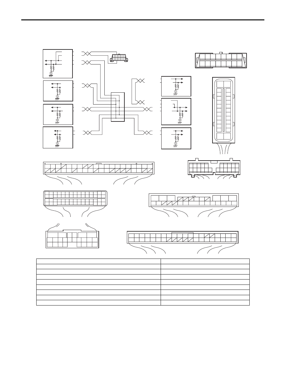
DTC No. 33: Control Module Communication Bus Off

S5JB0AA504020

Wiring Diagram

WHT

RED

WHT

RED

G44-18

G44-19

G44

[A]

[B]

[C]

[H]

[G]

1

2

3

4

5

6

7

8

9

10

11

14

15

16
36

34 33 32

30 29

24 23

37

18

19

20

G28-8

G28-10

WHT/BLU

WHT/BLU

WHT/RED

WHT/RED E23-4

E23-19

WHT

RED E03-12

E03-10

E03-6

E03-8

WHT

RED

E92-17

E92-7

WHT

RED

E91-22
E91-23

WHT

RED

RED

G31-1
G31-3

G31-4

6

5

16 15 14 13 12 11

4 3

24 23

21

22

10 9

8

7

2

1

19

20

18 17

E92

2 1

E23

3

4

18

19

5

6

7

10

11

17

20

47 46

49

50

51

21

22

52

16

25

9

24

14

29

55

57

5453

59

60

58

26

27

28

15
30

56

48

32 31

34

35

36

37

40

42

3938

44

45

43

41

33

12

13

23

8

1

2

3

4

5

6

7

8

9

10

11

17

1615141312

2221201918

G28

[F]

G31

E91

1

2

3

4

7

8

9

10

11

14

15

16
36

34

35

24 23

21

22

28 27

25

26

37

39 38

40

18 17

13 12

19

20

1

2

3

10

11

12

16

17

18

15 14 13

19

20

21

25

26

5

6

[E]

[D]

E03

15
16
17
18
19
20
21
22
23
24
25

2
3
4
5
6
7
8
9

10
11
12

1

13

14

26

8 7 6 5 4 3 2 1

9

10

11

12

13

14

15

16

G31-2

WHT

1

2

3

4

9

5

6

7

8

I5JB0AA50017-03

[A]: Keyless start control module connector (viewed from harness side)

1. BCM

[B]: ECM connector (viewed from harness side)

2. 4WD control module (if equipped)

[C]: TCM connector (viewed from harness side)

3. TCM (if equipped)

[D]: DLC (viewed from harness side)

4. Keyless start control module

[E]: ABS hydraulic unit / control module connector (viewed from harness side)

5. DLC

[F]: Combination meter connector (viewed from harness side)

6. ECM

[G]: 4WD control module connector (viewed from harness side)

7. ABS hydraulic unit / control module (if equipped)

[H]: BCM connector (viewed from harness side)

8. Combination meter
9. Junction connector

Keyless Start System:  10E-30

DTC Detecting condition and trouble area

DTC Confirmation Procedure

1) Clear DTC referring to “DTC Clearance”.
2) Start engine and run it for 1 min. or more.
3) Check DTC referring to “DTC Check”.

Troubleshooting

DTC detecting condition

Trouble area

Communication is not available with all control 
modules connected by CAN

• CAN communication circuit
• Combination meter
• Keyless start control module
• BCM
• 4WD control module (if equipped)
• ABS hydraulic unit / control module
• TCM (A/T model)
• ECM

Step

Action

Yes

No

1

Was “Keyless Start System Check” performed?

Go to Step 2.

Go to “Keyless Start 
System Check”
.

2

Control module connector check
1) Check connection of connectors of all control modules 

communicating by means of CAN.

2) Recheck DTC.

Is DTC No. 33 detected?

Go to Step 3.

Intermittent trouble. 
Check for intermittent 
referring to “Intermittent 
and Poor Connection 
Inspection in Section 
00”.

3

CAN communication circuit check
1) Turn ignition switch to OFF position.
2) Disconnect connectors of all control modules 

communicating by means of CAN.

3) Check CAN communication circuit between control 

modules for open, short and high resistance.

Is each CAN communication circuit in good condition?

Go to Step 4.

Repair circuit.

4

DTC check
1) Check DTC for BCM.

Is DTC U1073 detected?

Go to applicable DTC 
diag flow.

Go to Step 5.

10E-31 Keyless Start System: 

DTC No. 51 / No. 52 / No. 53: Driver Side / Passenger Side / Rear End Door Request Switch Failure

S5JB0AA504021

Wiring Diagram

5

DTC check
1) Turn ignition switch to OFF position.
2) Connect connectors of disconnected control modules 

communicating by means of CAN.

3) Disconnect connector of any one control module other 

than keyless start control module and combination 
meter.

4) Recheck DTC for keyless start control module.

Is DTC No.33 detected?

Using same method, 
disconnect connectors 
of control module other 
than keyless start 
control module and 
combination meter one 
by one to check if DTC 
No.33 is detected.
If DTC No.33 is 
detected even though 
connector of control 
module other than 
keyless start control 
module and 
combination meter is 
disconnected, substitute 
a known-good keyless 
start control module and 
recheck.

Check power and 
ground circuit of 
disconnected control 
module. If circuit is OK, 
substitute a known-
good disconnected 
control module and 
recheck.

Step

Action

Yes

No

G44

[A]

1

2

3

4

5

6

7

8

9

10

11

14

15

16
36

34 33 32

30 29

24 23

37

18

19

20

RED/BLK

BLU

YEL/RED

G44-16

G44-36

G44-32

12V

1

2

3

4

I5JB0AA50018-02

[A]: Keyless start control module connector “G44” (viewed from harness side)

3. Passenger side door request switch

1. Keyless start control module

4. Rear end door request switch

2. Driver side door request switch

Keyless Start System:  10E-32

DTC Detecting condition and trouble area

DTC Confirmation Procedure

1) Clear DTC referring to “DTC Clearance”.
2) Push request switch of each door.
3) Check DTC referring to “DTC Check”.

Troubleshooting

DTC detecting condition

Trouble area

DTC No. 51:
Input signal from driver side door request switch remains 
ON, unchanged for 10 minutes or longer.
DTC No. 52:
Input signal from passenger side door request switch 
remains ON, unchanged for 10 minutes or longer.
DTC No. 53:
Input signal from rear end door request switch remains 
ON, unchanged for 10 minutes or longer.

• Driver side door request switch and its circuit
• Passenger side door request switch and its circuit
• Rear end door request switch and its circuit
• Keyless start control module

Step

Action

Yes

No

1

Was “Keyless Start System Check” performed?

Go to Step 2.

Go to “Keyless Start 
System Check”
.

2

Keyless start control module voltage check
1) Turn ignition switch to OFF position.
2) Disconnect connector from each door request switch.
3) Check for proper connection to all terminals of each door 

request switch connector.

4) If OK, measure voltage between “RED/BLK”, “BLU” or 

“YEL/RED” terminal of related door request switch 
connector and vehicle body ground.

Is voltage 10 – 14 V?

Go to Step 3.

Go to Step 4.

3

Request switch check
1) Check related door request switch for function referring 

to “Front Door (Driver and Passenger Side) Rear End 
Door Request Switch Inspection”.

Is each switch in good condition?

Check for open and 
high resistance in 
ground circuit of related 
door request switch. If 
ground circuit is OK, 
substitute a known-
good keyless start 
control module and 
recheck.

Replace request switch.

4

Wire harness check
1) Disconnect connector from keyless start control module.
2) Check for open, short and high resistance in related 

circuit.
• Between “RED/BLK” terminal of driver side door 

request switch connector and “G44-16” terminal of 
keyless start control module connector

• Between “BLU” terminal of passenger side door 

request switch connector and “G44-36” terminal of 
keyless start control module connector

• Between “YEL/RED” terminal of rear end door request 

switch connector and “G44-32” terminal of keyless 
start control module connector

Is it in good condition?

Substitute a known-
good keyless start 
control module and 
recheck.

Repair circuit.


Content   ..  429  430  431  432   ..