Suzuki Grand Vitara JB416 / JB420. Manual - part 428


  Index      Suzuki     Suzuki Grand Vitara JB416 / JB420- service repair manual


Search            


Content   ..  426  427  428  429   ..


Suzuki Grand Vitara JB416 / JB420. Manual - part 428


10E-17 Keyless Start System: 

Reference waveform No. 1
Driver, passenger and rear end door antenna request 
signals (Request signal (1) transmitted by each door 
antenna when each door request switch is pushed)

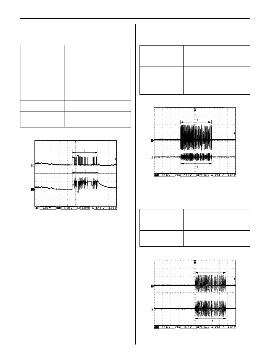
Reference waveform No. 2
Center antenna signal
(Request signal (1) transmitted by center antenna when 
each door request switch is pushed)

Reference waveform No. 3
Luggage room antenna signal
(Request signal (1) transmitted by luggage room 
antenna when each door request switch is pushed)

Measurement 
terminal

Driver side door antenna
• CH1: “G44-2” to “G44-9”
• CH2: “G44-1” to “G44-9”
Passenger side door antenna
• CH1: “G44-24” to “G44-9”
• CH2: “G44-23” to “G44-9”
Rear end door antenna
• CH1: “G44-4” to “G44-9”
• CH2: “G44-3” to “G44-9”

Oscilloscope setting CH1: 5 V/DIV, CH2: 5 V/DIV

TIME: 40 ms/DIV

Measurement 
condition

Request switch of each door is 
pushed with remote controller 
carried

I4RS0BA50015-02

Measurement 
terminal

CH1: “G44-6” to “G44-9”
CH2: “G44-5” to “G44-9”

Oscilloscope setting CH1: 10 V/DIV, CH2: 2 V/DIV

TIME: 20 ms/DIV

Measurement 
condition

• Ignition knob switch of steering 

lock unit is pushed

• Request switch of each door is 

pushed with remote controller 
carried

Measurement 
terminal

CH1: “G44-8” to “G44-9”
CH2: “G44-7” to “G44-9”

Oscilloscope setting CH1: 10 V/DIV, CH2: 10 V/DIV

TIME: 20 ms/DIV

Measurement 
condition

Request switch of each door is 
pushed with remote controller 
carried

I5JB0AA50024-03

I5JB0AA50025-02

Keyless Start System:  10E-18

Reference waveform No. 4
CAN communication signals for combination meter
(CAN signal communicated between keyless start 
control module and combination meter when ignition 
switch is turned ON)

Reference waveform No. 5
Steering lock unit signal
(Signal (1) communicated between keyless start control 
module and steering lock unit when measurement 
condition described below applies)

Reference waveform No. 6
Driver and passenger side door lock switch signals.
(This signal indicates door lock status.) 
In case the position of driver and passenger side door 
lock is changed from the unlock to the lock.

Measurement 
terminal

CH1: “G44-19” to “G44-9”
CH2: “G44-18” to “G44-9”

Oscilloscope setting CH1: 1 V/DIV, CH2: 1 V/DIV

TIME: 40 

µs/DIV

Measurement 
condition

Ignition switch is at ON position

1. CAN communication line signal (high)
2. CAN communication line signal (low)

Measurement 
terminal

CH1: “G44-29” to “G44-9”

Oscilloscope setting CH1: 2 V/DIV

TIME: 10 ms/DIV

Measurement 
condition

• Ignition knob switch of steering 

lock unit is pushed

• Request switch of each door is 

pushed with remote controller 
carried

I4RS0BA50018-02

I5JB0AA50026-02

Measurement 
terminal

Driver side door lock switch
• CH1: “G42-33” to “G42-9”
Passenger side door lock switch
• CH2: “G42-37” to “G42-9”

Oscilloscope setting CH1: 2 V/DIV CH2: 2 V/DIV

TIME: 1 s/DIV

Measurement 
condition

Press lock side of manual door 
lock switch

1. Unlock signal

2. Lock signal

I5JB0AA50027-02

10E-19 Keyless Start System: 

In case the position of passenger side door lock is 
changed from the lock to the unlock when the position of 
driver and passenger side door is at the lock

In case the position of driver side door lock is changed 
from the lock to the unlock when the position of driver 
and passenger side door is at the lock.

In case the position of driver and passenger side door 
lock is changed from the lock to the unlock.

Measurement 
terminal

Driver side door lock switch
• CH1: “G42-33” to “G42-9”
Passenger side door lock switch
• CH2: “G42-37” to “G42-9”

Oscilloscope setting CH1: 2 V/DIV CH2: 2 V/DIV

TIME: 400 ms/DIV

Measurement 
condition

Driver door is at lock position and 
passenger side door is at unlock 
position

1. Lock signal

2. Unlock signal

I5JB0AA50028-02

Measurement 
terminal

Driver side door lock switch
• CH1: “G42-33” to “G42-9”
Passenger side door lock switch
• CH2: “G42-37” to “G42-9”

Oscilloscope setting CH1: 2 V/DIV CH2: 2 V/DIV

TIME: 400 ms/DIV

Measurement 
condition

Driver door is at unlock position 
and passenger side door is at 
lock position

1. Lock signal

2. Unlock signal

Measurement 
terminal

Driver side door lock switch
• CH1: “G42-33” to “G42-9”
Passenger side door lock switch
• CH2: “G42-37” to “G42-9”

Oscilloscope setting CH1: 2 V/DIV CH2: 2 V/DIV

TIME: 400 ms/DIV

Measurement 
condition

Driver door is at unlock position 
and passenger side door is at 
lock position

1. Lock signal

2. Unlock signal

I5JB0AA50029-02

I5JB0AA50030-03

Keyless Start System:  10E-20

No DTC Detection After Performing DTC Check

S5JB0AA504022

Wiring Diagram

BLK

G44-9

G44-15

G44-14

G44-16

G44-20
G44-29
G44-30

G44-10

G44-34

G44-11

WHT/BLK

WHT

WHT

RED/BLK

YEL

5V

5V

5V

5V

5V

12V

12V

WHT

RED

WHT

RED

G44-18

G44-19

BLU/RED

BRN/RED

BLK/YEL

BRN/YEL

ORN

G22-3

G22-4

G22-5

G22-2

G22-1

G22-6

G22-7
G22-8

WHT

WHT

G44

[A]

[B]

1

2

3

4

5

6

7

8

9

10

11

14

15

16
36

34 33 32

30 29

24 23

37

18

19

20

WHT

G28-8

G28-10

G28-14

I5JB0AA50013-03

[A]: Keyless start control module connector (viewed from harness side)

3. Steering lock solenoid

7. Combination meter

[B]: To each control module

4. Ignition knob switch

8. Key indicator lamp

1. Keyless start control module

5. Key reminder switch

9. Junction box

2. Steering lock unit

6. Driver side door request switch

10. Junction connector


Content   ..  426  427  428  429   ..