Suzuki Grand Vitara JB416 / JB420. Manual - part 376


  Index      Suzuki     Suzuki Grand Vitara JB416 / JB420- service repair manual


Search            


Content   ..  374  375  376  377   ..


Suzuki Grand Vitara JB416 / JB420. Manual - part 376


9C-13 Instrumentation / Driver Info. / Horn: 

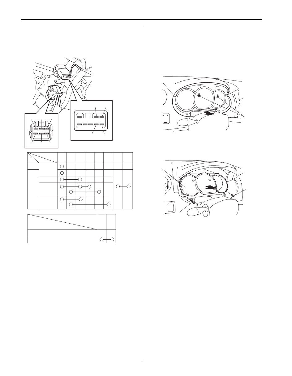
Ignition Switch Inspection

S5JB0A9306002

• Check for continuity between terminals at each switch 

position. If check result is not as specified, replace 
switch.

Combination Meter Removal and Installation

S5JB0A9306003

Removal

1) Disconnect negative (–) cable at battery.
2) Remove screws (1) fastening combination meter 

cluster panel.

3) Remove combination meter cluster panel (2) pulling 

it in arrow direction shown in figure.

4) Remove screws (1) fastening combination meter.
5) Remove combination meter (2) pulling it arrow 

direction as shown.

Installation
Reverse removal procedure.

Position

Terminal

LOCK

ACC

ON

START

OUT    

IN

K2

K1

ST

IG2

IG1

ACC

B1

B2

Ignition knob switch
(with keyless start system only)

ST

IG2

IG1

ACC

B1

B2

K2

K1

P2

P1

Terminal

OFF (ignition knob switch released) 

ON  (ignition knob switch pushsed)

P1

P2

Key

I5JB0A930004-01

2

1

I5JB0A930005-04

1

2

1

I5JB0A930006-04

Instrumentation / Driver Info. / Horn:  9C-14

Fuel Level Sensor Removal and Installation

S5JB0A9306004

Removal
Remove fuel pump assembly referring to “Fuel Pump 
Assembly Removal and Installation in Section 1G”.

Installation
Install fuel pump assembly referring to “Fuel Pump 
Assembly Removal and Installation in Section 1G”.

Fuel Level Sensor Inspection

S5JB0A9306005

• Check that resistance between terminals “a” and “b” 

of fuel level sensor changes with change of float 
position.

• Check resistance between terminals “a” and “b” at 

each float position in the following.
If the measured value is out of specification, replace 
fuel pump and/or sub fuel level sensor.

Main fuel level sensor [A] specifications

Sub fuel level sensor [B] specifications

Oil Pressure Switch Removal and Installation

S5JB0A9306006

For removal and installation, refer to “Oil Pressure 
Check: For M16A Engine with VVT in Section 1E” 
or “Oil 
Pressure Check: For J20 Engine in Section 1E”.

Float position

Resistance (

)

M16 

engine 

model

Full Upper 

“C”

193.7 mm 

(7.626 in.)

19.0 – 21.0

Full Lower 

“D”

42.2 mm 

(1.661 in.)

111.9 – 115.3

J20 

engine 

model

Full Upper 

“C”

196.8 mm 

(7.748 in.)

19.0 – 21.0

Full Lower 

“D”

34.9 mm 

(1.374 in.)

129.0 – 132.4

Float position

Resistance (

)

M16 

engine 

model

Full Upper 

“C”

48.1 mm 

(1.894 in.)

19.0 – 21.0

Full Lower 

“D”

252.8 mm 

(9.953 in.)

164.7 – 168.1

J20 

engine 

model

Full Upper 

“C”

64.1 mm 

(2.524 in.)

19.0 – 21.0

Full Lower 

“D”

244.8 mm 

(9.638 in.)

147.6 – 151.0

1. Fuel pump
2. Float

“c”

“d”

“d”

[A]

[B]

“b”

“a”

“b”

“a”

1

2

“c”

2

I5JB0A930030-02

9C-15 Instrumentation / Driver Info. / Horn: 

Oil Pressure Switch Inspection

S5JB0A9306007

1) Disconnect oil pressure switch (1) lead wire.
2) Check for continuity between oil pressure switch 

terminal (2) and cylinder block (3) as shown.
If check result is not as specified, replace oil 
pressure switch (1).

Oil pressure sensor specification
During engine running: No continuity
At engine stop: Continuity

Engine Coolant Temperature (ECT) Sensor 
Inspection

S5JB0A9306010

Check engine coolant temperature sensor for resistance, 
refer to “Engine Coolant Temperature (ECT) Sensor 
Inspection in Section 1C”.

Brake Fluid Level Switch Inspection

S5JB0A9306011

Check for continuity between terminals of brake fluid 
level switch coupler (1). If found defective, replace 
switch.

Brake fluid level switch specification
OFF position (float up): No continuity
ON position (float down): Continuity

Parking Brake Switch Inspection

S5JB0A9306012

Check for continuity between parking brake switch 
terminal and body ground as shown in figure. If found 
defective, replace switch.

Parking brake switch specification
OFF position (parking brake released): No continuity
ON position (parking brake lever pulled up): 
Continuity

[A]: J20 engine model

4. Engine oil filter

[B]: M16 engine model

1

1

4

[A]

[B]

I5JB0A930007-02

1. Parking brake switch
2. Parking brake lever

1

I5JB0A930008-01

1

2

I5JB0A930009-01

Instrumentation / Driver Info. / Horn:  9C-16

Door Switch (Front / Rear / Rear End Door) 
Inspection

S5JB0A9306013

Remove door switch from body and check switch for 
continuity. If found defective, replace switch.

Door switch (front / rear / rear end door) 
specification
OFF position (Door closed): No continuity
ON position (Door open): Continuity

Outside Air Temperature Sensor Removal and 
Installation (If Equipped)

S5JB0A9306015

Removal

1) Disconnect negative (–) cable at battery.
2) Remove front bumper referring to “Front Bumper 

Components in Section 9K”.

3) Disconnect connector (1) from outside air 

temperature sensor (2).

4) Remove outside air temperature sensor (2) from 

front bumper (3).

Installation
Reverse removal procedure for installation.

Outside Air Temperature Sensor Inspection (If 
Equipped)

S5JB0A9306016

Measure resistance of outside air temperature sensor 
using an ohmmeter.
If resistance is out of specification, replace outside air 
temperature sensor.

Outside air temperature sensor resistance
1.62 k

 – 1.78 k at 25 °C (77 °F)

I3RH0A930004-01

1

2

3

I5JB0A930010-01

“A”: Resistance
“B”: Temperature

“B”

“A”

5.50

1.70

0

32

25
77

F

I4RS0A930017-01


Content   ..  374  375  376  377   ..