Suzuki Grand Vitara JB416 / JB420. Manual - part 325


  Index      Suzuki     Suzuki Grand Vitara JB416 / JB420- service repair manual


Search            


Content   ..  323  324  325  326   ..


Suzuki Grand Vitara JB416 / JB420. Manual - part 325


8B-96 Air Bag System: 

Repair Instructions

Disabling Air Bag System

S5JB0A8206001

1) Turn steering wheel so that vehicle’s wheels (front 

tires) are pointing straight ahead.

2) Disconnect negative (–) cable at battery.
3) Turn ignition switch to “LOCK” position and remove 

key.

4) Remove “A/B” fuse from fuse box.
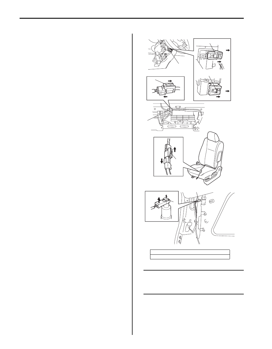
5) Remove steering column cover and disconnect 

yellow connector (1) of contact coil and combination 
switch assembly as follows.
a) Release locking of lock slider (2).
b) After unlocked, disconnect connector.

6) Remove grove box from instrument panel and 

disconnect yellow connector (3) for passenger air 
bag as follows.
a) Release locking of lock slider (2).
b) After unlocked, disconnect connector.

7) If equipped with side-air bag (inflator) module, 

disconnect yellow connector of side-air bag (inflator) 
module under front seat cushion (4).
a) Release locking of lock slider (2).
b) After unlocked, disconnect connector.

8) If equipped with side curtain-air bag (inflator) 

module, remove quarter inner trim and disconnect 
black connector (5) of side curtain-air bag (inflator) 
module.
a) Unlock button (6).
b) With lock button unlocked, disconnect connector.

NOTE
With “A/B” fuse removed and ignition switch 
ON, “AIR BAG” warning lamp will be ON.
This is normal operation and does not 
indicate air bag system malfunction.


[A]: For vehicle without cruise control system
[B]: For vehicle with cruise control system

2

b)

a)

a)

b)

[A]

[B]

2

2

a)

b)

a)

b)

5

6

a)

b)

2

3

1

I5JB0A820067-01

Air Bag System:  8B-97

Enabling Air Bag System

S5JB0A8206002

1) Confirm that battery negative (–) cable is 

disconnected.

2) Turn ignition switch to “LOCK” position and remove 

key.

3) Connect yellow connector (1) of contact coil and 

combination switch assembly by pushing connector 
till click is heard from it.

4) Connect yellow connector (1) of passenger air bag 

(inflator) module by pushing connector till click is 
heard from it.

5) Install glove box.
6) If equipped with side-air bag (inflator) module, 

connect yellow connector (1) of side-air bag (inflator) 
module by pushing connector till click is heard from 
it.

7) If equipped with side curtain-air bag (inflator) 

module, connect black connector (1) securely as 
shown in figure.
a) Connect connector.
b) Lock connector with lock button (2).

8) Install “A/B” fuse to fuse box.
9) Connect negative (–) cable at battery.

10) Turn ignition switch to ON position and verify that 

“AIR BAG” warning lamp flashes 6 times and then 
turns OFF. If it does not operate as described, 
perform “Air Bag Diagnostic System Check”.

[A]: For vehicle without cruise control system
[B]: For vehicle with cruise control system

[A]

[B]

1

I5JB0A820068-01

1

I5JB0A820069-01

1

I5JB0A820070-01

a)

b)

2

1

I5JB0A820071-01

8B-98 Air Bag System: 

SDM Removal and Installation

S5JB0A8206003

WARNING

!


During service procedures, be very careful 
when handling a Sensing and Diagnostic 
Module (SDM).
Be sure to read “Precautions on Service and 
Diagnosis of Air Bag System” 
before starting 
to work and observe every precaution during 
work. Neglecting them may result in personal 
injury or inactivation of the air bag system 
when necessary.


Removal

1) Disconnect negative cable at battery.
2) Disable air bag system referring to “Disabling Air 

Bag System”.

3) Remove console rear panel referring to “Console 

Box Components in Section 9H”.

4) Disconnect SDM connector (1) from SDM (2).

5) Remove SDM (1) from vehicle.

Installation

1) Check that none of the following faulty conditions 

exists.
• Bend, scratch, deformity in vehicle body where 

SDM is mounted.

• Foreign matter or rust on mating surface of vehicle 

body where SDM is mounted.

2) Install SDM (2) to vehicle.

CAUTION

!


Ensure that arrow on the SDM is pointing 
toward the front of the vehicle.


3) Tighten SDM bolts (1) to specified torque.

Tightening torque
SDM bolt (a):  6 N·m (0.6 kgf-m, 4.5 lb-ft)

4) Connect SDM connector (1) to SDM (2) securely.

5) Install console rear panel.
6) Enable air bag system referring to “Enabling Air Bag 

System”.

7) Connect negative cable at battery.

[A]: Without side-air bag and curtain-air bag
[B]: With side-air bag and curtain-air bag

[A]

[B]

1

1

2

2

I5JB0A820109-01

1

I5JB0A820073-01

A: Vehicle forward

3. Ground for air bag system

[A]: Without side-air bag and curtain-air bag
[B]: With side-air bag and curtain-air bag

2

1, (a)

3

A

I5JB0A820074-02

[A]

[B]

1

1

2

2

I5JB0A820072-01

Air Bag System:  8B-99

SDM Inspection

S5JB0A8206004

WARNING

!


During service procedures, be very careful 
when handling a Sensing and Diagnostic 
Module (SDM).
Be sure to read “Precautions on Service and 
Diagnosis of Air Bag System” 
before starting 
to work and observe every precaution during 
work. Neglecting them may result in personal 
injury or inactivation of the air bag system 
when necessary.


CAUTION

!


• Do not connect a tester whatever type it 

may be.

• Never repair or disassemble SDM.
• If SDM has been dropped, it should be 

replaced.


If any faulty condition is found in the following checks, 
replace.
• Check SDM for dents, cracks or deformation.
• Check SDM connector for damage, cracks or lock 

mechanism.

• Check SDM terminal for bend, corrosion or rust.

Driver Air Bag (Inflator) Module Removal and 
Installation

S5JB0A8206005

WARNING

!


When handling an air bag (inflator) module, 
be sure to read “Precautions on Handling 
and Storage of Air Bag System Components” 
and observe each instruction. Failure to 
follow them could cause a damage to the air 
bag (inflator) module or result in personal 
injury.


Removal

1) Disconnect negative cable at battery.
2) Disable air bag system. Refer to “Disabling Air Bag 

System”.

3) Remove steering wheel side caps (2).
4) Loosen driver air bag (inflator) module mounting 

bolts (1) till it turns freely, pull them out and fix them 
to bolt clamps.

5) Remove air bag (inflator) module from steering 

wheel.

6) Disconnect driver air bag (inflator) module connector 

(1) of driver air bag (inflator) module as shown in 
figure.
a) Unlock lock button (2).
b) With lock button unlocked, disconnect connector.

1

1

2

2

I5JB0A820075-01

a)

b)

2

1

I5JB0A820076-01


Content   ..  323  324  325  326   ..