Suzuki Grand Vitara JB416 / JB420. Manual - part 321


  Index      Suzuki     Suzuki Grand Vitara JB416 / JB420- service repair manual


Search            


Content   ..  319  320  321  322   ..


Suzuki Grand Vitara JB416 / JB420. Manual - part 321


8B-80 Air Bag System: 

2

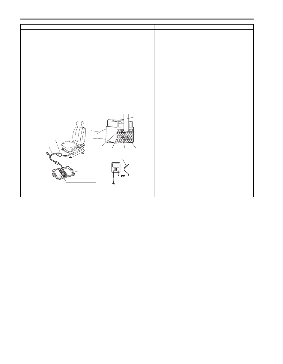
1) With ignition switch OFF, disconnect special tools and 

SDM connector “L33”.

2) Release shorting bar in SDM connector inserting release 

tool (1) included in special tool (A).

3) Measure resistance between “L33-1” and body ground, 

and between “L33-2” and body ground (for DTC B1323) 
or “L33-3” and body ground, and between “L33-4” and 
body ground (for DTC B1327) with connected special 
tools (B) and (C).

Special tool
(A):  09932–76010
(B):  09932–75010
(C):  09932–78340

Is resistance infinity?

Substitute a known-
good SDM and recheck.

DTC B1323: Repair 
short from “GRY/RED” 
or “GRY” wire circuit to 
ground in floor harness.
DTC B1327: Repair 
short from “BRN/WHT” 
or “BRN” wire circuit to 
ground in floor harness.

Step

Action

Yes

No

“L25”, “L30”

(C)

(B)

STEERING WHEEL

“L33-1”

“L33-2” “L33-3” “L33-4”

(A)

1, (A)

I5JB0A820047-01

Air Bag System:  8B-81

NOTE
Upon completion of inspection and repair work, perform the following items.
• Reconnect all air bag system components, ensure all components are properly mounted.
• Clear DTCs referring to “DTC Clearance”, if any
.
• Repeat “Air Bag Diagnostic System Check” 
to confirm that the trouble has been corrected.


3

1) With ignition switch OFF, disconnect special tools (B) 

and (C) then reconnect connector “L25” or “L30”.

2) Disconnect side-air bag (inflator) module connector 

“Q02” or “Q03” from side-air bag (inflator) module.

3) Check proper connection to side-air bag (inflator) 

module at terminal in connector.

4) If OK, then connect special tools (A), (B) and (C) to side-

air bag (inflator) connector.

Special tool
(A):  09932–76010
(B):  09932–75010
(D):  09932–78310

5) Check SDM DTC.

With ignition switch ON, is DTC B1323 or B1327 still 
indicated?

DTC B1323: Repair 
short from “GRY/RED” 
or “GRY” wire circuit to 
ground in seat harness.
DTC B1327: Repair 
short from “BRN/WHT” 
or “BRN” wire circuit to 
ground in seat harness.

Replace side-air bag 
(inflator) module 
referring to “Side-Air 
Bag (Inflator) Module 
Removal and 
Installation”
.

Step

Action

Yes

No

“L25”, “L30”

STEERING WHEEL

(B)

(D)

(A)

“Q02”, “Q03”

I5JB0A820046-02

8B-82 Air Bag System: 

DTC B1324 / B1328: Left / Right Side-Air Bag Initiator Circuit Short to Power Circuit

S5JB0A8204033

Wiring Diagram
Refer to “DTC B1321 / B1325: Left / Right Side-Air Bag Initiator Circuit Resistance High”.

CAUTION

!


Be sure to observe instructions under CAUTION in “Air Bag Diagnostic System Check Flow”.


DTC Will Set when
The voltage measured at side-air bag (left or right) initiator circuit is above a specified value for specified time.

Flow Test Description
Step 1: Check whether malfunction is in side-air bag (inflator) module.
Step 2: Check side-air bag initiator circuit in floor harness.
Step 3: Check side-air bag initiator circuit in seat harness.

DTC Troubleshooting

Step

Action

Yes

No

1

1) With ignition switch OFF, disconnect side-air bag 

(inflator) module connector under front seat cushion.

2) Check proper connection to left or right side-air bag 

(inflator) module at terminals in “L25” or “L30” connector.

3) If OK, then connect special tools (B) and (C) to side-air 

bag (inflator) module connector disconnected at the Step 
1.

Special tool
(B):  09932–75010
(C):  09932–78340

4) Check SDM DTC.

With ignition switch ON, is DTC B1324 or B1328 still 
indicated?

Go to Step 2.

Go to Step 3.

“L25”, “L30”

(C)

(B)

STEERING WHEEL

I4RS0A820032-01

Air Bag System:  8B-83

2

1) With ignition switch OFF, disconnect special tools (B), 

(C) and SDM connector “L33”.

2) Release shorting bar in SDM connector inserting release 

tool (1) included in special tool (A).

3) Measure voltage between “L33-1” and body ground, and 

between “L33-2” and ground (for DTC B1324) or “L33-3” 
and body ground, and between “L33-4” and body ground 
(for DTC B1328) with connected special tools (B) and 
(C).

Special tool
(A):  09932–76010
(B):  09932–75010
(C):  09932–78340

With ignition switch ON, is voltage 1 V or less?

Substitute a known-
good SDM and recheck.

DTC B1324: Repair 
short from “GRY/RED” 
or “GRY” wire circuit to 
power circuit in floor 
harness.
DTC B1328: Repair 
short from “BRN/WHT” 
or “BRN” wire circuit to 
power circuit in floor 
harness.

Step

Action

Yes

No

(A)

“L25”, “L30”

(C)

(B)

STEERING WHEEL

“L33-1”

“L33-2”

“L33-3” “L33-4”

1, (A)

I5JB0A820048-01


Content   ..  319  320  321  322   ..