Suzuki Grand Vitara JB416 / JB420. Manual - part 245


  Index      Suzuki     Suzuki Grand Vitara JB416 / JB420- service repair manual


Search            


Content   ..  243  244  245  246   ..


Suzuki Grand Vitara JB416 / JB420. Manual - part 245


5A-114 Automatic Transmission/Transaxle: 

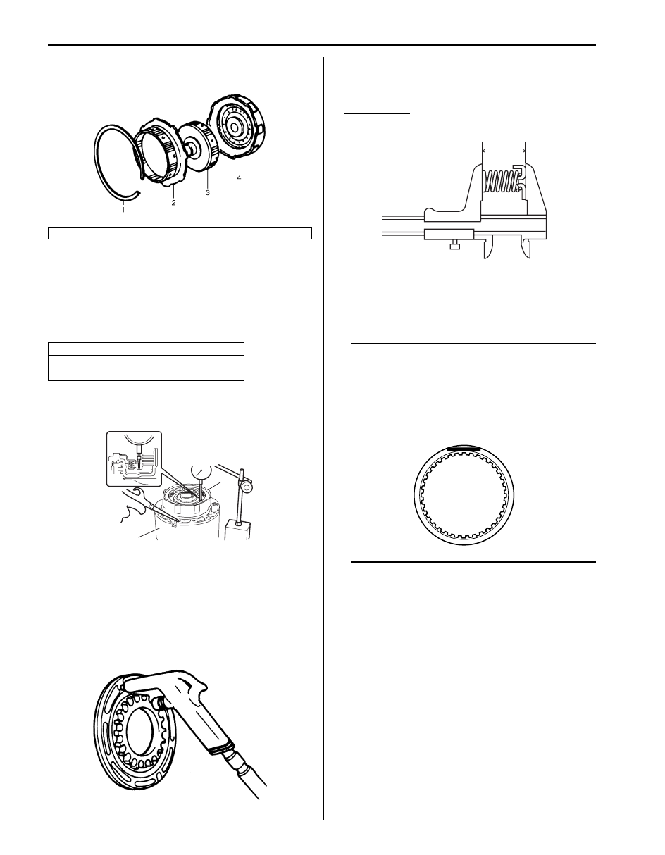
4) Install forward clutch hub (3), direct clutch hub (2) 

and retaining ring (1) in that order.

5) Install forward clutch (2) to O/D case (1). Apply 

compressed air (400 – 800 kPa, 4 – 8 kg/cm

2

, 57 – 

113 psi) to oil hole at the right of cut in O/D case and 
measure movement of forward clutch piston.
If measured value is not within standard range, 
select another plate with suitable thickness from the 
list below and replace it.

Standard forward clutch piston movement
1.40 – 1.70 mm (0.055 – 0.067 in.)

Forward Clutch Inspection

S5JB0A5106079

Forward Clutch Piston
• Shake piston to check that ball is not stuck.
• Blow low pressure air to check ball section for 

leakage.

Forward Clutch Piston Return Spring
• Measure free length.

Standard free length of forward clutch piston 
return spring
24.81 mm (0.977 in.)

Clutch Plate and Disc
• Check that sliding surface of discs and plate are not 

worn or burnt. If necessary, replace them.

NOTE

• If disc lining is exfoliated, discolored or 

worn hardly, replace all discs.

• If only a part of printed numbers is 

corroded, replace all discs.

• Before assembling new discs, soak them 

in A/T fluid for at least 15 minutes.


4. Input shaft

Thickness

1.75 – 1.85 mm (0.069 – 0.073 in.)
1.95 – 2.05 mm (0.077 – 0.081 in.)

IYSQ01510151-01

2

1

I5JB0A510150-01

IYSQ01510152-01

I5JB0A510171-01

I4JA01512210-01

Automatic Transmission/Transaxle:  5A-115

Direct Clutch Components

S5JB0A5106080

Direct Clutch Disassembly and Assembly

S5JB0A5106081

Disassembly

1) Remove direct clutch assembly from center support 

and then remove retaining ring.

2) Remove clutch backing plate (1) and then remove 

clutch disc (3) and clutch plate (2).

10

11

3

8

6

5

4

2

1

3

9

7

FLD

FLD

FLD

8

FLD

I5JB0A510112-01

1. Bearing race

5. Clutch disc

9. Direct clutch piston

: Apply A/T fluid.

2. Bearing

6. Clutch plate

10. Direct clutch inner piston

3. Retaining ring

7. Return spring

11. Direct clutch cylinder

4. Clutch backing plate

8. O-ring

: Do not reuse.

IYSQ01510156-01

2

1

3

I5JB0A510114-01

5A-116 Automatic Transmission/Transaxle: 

3) Using special tool and hydraulic press (1), compress 

direct clutch piston return spring (3) and remove 
retaining return spring ring (2).

Special tool
(A):  09926–98310 

CAUTION

!


Be careful when applying pressure, for 
overpressure will cause plate section of 
piston return spring to deform.


4) Remove direct clutch piston return spring.
5) Install direct clutch cylinder to center support.

Remove direct clutch piston by blowing air into the 
second hole from the left as shown in the figure. 
Also, remove direct clutch inner piston by blowing air 
into hole at the extreme right. And then remove O-
rings from pistons.

Assembly
Assemble each component by reversing disassembly 
procedure and noting the following points.
• Always use new O-ring and apply A/T fluid before 

installation.

• Do not align opening in retaining ring (2) with lug of 

direct clutch piston return spring at retainer.

Special tool
(A):  09926–98310 

• Use care so that direct clutch piston return spring will 

not fall or tilt.

CAUTION

!


Be careful when applying pressure, for 
overpressure will cause plate section of 
piston return spring to deform.


• Do not match opening (1) in retaining back plate ring 

with cutout (2) in direct clutch cylinder.

• Install clutch backing plate with its grooved side (1) 

facing the front.

IYSQ01510158-01

IYSQ01510159-01

1. Hydraulic press

[A]: Front

IYSQ01510160-01

IYSQ01510161-01

I5JB0A510115-01

Automatic Transmission/Transaxle:  5A-117

• Install direct clutch assembly (1) to center support (2) 

and with compressed air (400 – 800 kPa, 4 – 8 kg/
cm

2

, 57 – 113 psi) applied to oil hole (3), measure 

stroke of direct clutch piston as shown in the figure.
If it is not within standard range, select another plate 
with suitable thickness from the list below and replace 
it.

Direct clutch piston standard stroke
0.90 – 1.30 mm (0.035 – 0.051 in.)

Direct Clutch Inspection

S5JB0A5106082

• Measure inside diameter of direct clutch cylinder 

bushing. If inside diameter exceeds limit, replace 
direct clutch cylinder.

Direct clutch cylinder bushing inside diameter 
standard
23.062 – 23.088 mm (0.9080 – 0.9090 in.)

Direct Clutch Piston Return Spring
• Measure free length.

Standard free length of direct clutch piston return 
spring
24.25 mm (0.955 in.)

Direct Clutch Piston
• Shake piston to check that ball is not stuck.
• Apply air pressure and check that there is no leakage.

Clutch Disc and Plate
Check that sliding surface of discs and plate are not 
worn or burnt. if necessary, replace them.

NOTE

• If disc lining is exfoliated, discolored or 

worn hardly, replace all discs.

• If only a part of printed numbers is 

corroded, replace all discs.

• Before assembling new discs, soak them 

in A/T fluid for at least 15 minutes.


Identification No.

Thickness

No identification

3.925 – 4.050 mm

(0.155 – 0.159 in.)

“B”

3.675 – 3.800 mm

(0.145 – 0.150 in.)

“A”

3.475 – 3.600 mm

(0.137 – 0.142 in.)

2

3

1

I5JB0A510113-01

I5JB0A510156-01

I5JB0A510171-01

IYSQ01510163-01

I4JA01512210-01


Content   ..  243  244  245  246   ..