Suzuki Grand Vitara JB416 / JB420. Manual - part 200
4A-17 Brake Control System and Diagnosis:
Brake Booster Removal and Installation
S5JB0A4106020
Removal
1) Disconnect brake pipes from ABS actuator if
equipped.
2) Remove master cylinder assembly, referring to
“Master Cylinder Assembly Removal and
Installation”.
3) Disconnect brake vacuum hose from brake booster.
4) Remove clip (2) and the disconnect clevis pin (3).
5) Remove attaching nuts (1) and then remove booster
as shown in the figure.
CAUTION
!
Never disassemble brake booster.
Disassembly will spoil its original function. If
is found faulty, replace it with new one.
Installation
NOTE
• Check length of push rod clevis (2). Refer
to “Booster Push Rod Clevis Adjustment”.
1) Install gasket to booster and then install booster to
dash panel as shown in the figure. Then connect
booster push rod clevis (2) to pedal arm (3) with
clevis pin inserting from left (4) and clip (5).
2) Tighten booster attaching nuts (6) to the specified
torque.
Tightening torque
Booster attaching nut (a): 13 N·m (1.3 kgf-m, 9.5
lb-ft)
3) Connect brake vacuum hose to brake booster.
4) Install master cylinder referring to “Master Cylinder
Assembly Removal and Installation”.
5) After installing, fill reservoir with specified brake fluid
and bleed brake system. Check each installed part
for fluid leakage and perform brake test.
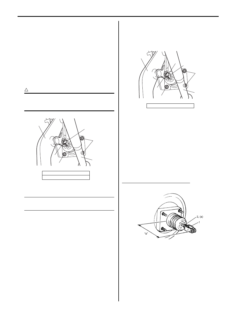
Booster Push Rod Clevis Adjustment
S5JB0A4106023
Install push rod clevis (1) so that measurement “a” is
obtained and torque nut (2) to specification.
Tightening torque
Clevis pin lock nut (a): 26 N·m (2.6 kgf-m, 19.0 lb-ft)
Clevis installing position (length “a”)
“a”: 133.5 – 134.5 mm (5.26 – 5.30 in.)
4. Steering column
5. Brake pedal arm
5
2
1
4
3
1
I5JB0A410024-01
1. Steering column
3
5
6,(a)
1
4
6,(a)
2
I5JB0A410025-01
IYSQ01410050-01